
Switch User Manual

Chapter 3. Identifying the Components
May 2002 T-38324-A Page 3-17
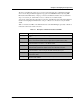
Table 3-2 describes the LEDs.
Table 3-2. Description of LEDs on the Side of the Interbus-S Module
LED Name Description
24V Power Supply
Steady yellow light indicates the +24V power supply is connected to
the Interbus-S module.
Remote Bus Connected
Steady green light indlicates the remote bus is connected.
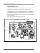
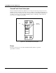
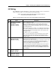
Figure 3-2 shows the position of the six-pin input terminal, nine-pin output terminal and LEDs on the
top of the Interbus-S module. Each LED lights up steadily to indicate the current state of I/O
connections.
Figure 3-12. Interbus-S Module Top View
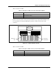
Table 3-3 describes the LEDs.
Table 3-3. Description of LEDs on the Top of the Interbus-S Module
LED Name Description
Data Refresh (BA)
Steady green light indicates data is being refreshed.
Remote Bus Disabled (RD)
Steady red light indicates the remote bus is disabled.
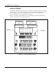
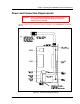
BA RD
IN
OUT
Data Refresh
LED
Remote Bus
Disabled LED