
Switch User Manual


CS4000 Mini Controller with Ethernet
Page
4-6
T-38324-A 39-30-38324
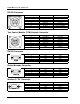
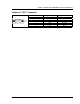
Table 3-1. 19-Position Remote I/O Connector Pinout Signal Names and Descriptions (Continued)
Pin Signal Description
E Limit Set Select B0 input
(Red wire - internal)
(Orange wire - external)
When Set Defaults is clicked, VS sets these three inputs to select which
of the eight internal limit (or parameter) sets are used for a fastening
cycle, as follows:
F Limit Set Select B1 input
(Green wire - internal)
(Blue wire - external)
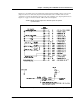
Limit Set B2 Input B1 Input B0 Input
1 inactive inactive inactive
2 inactive inactive active
3 inactive active inactive
4 inactive active active
5 active inactive inactive
6 active inactive active
7 active active inactive
8 active active active
G Limit Set Select B2 input
(Orange wire - internal)
(White/Black wire - external))
After a fastening cycle has started, changing the state of these inputs
does not change which limit set the CS4000 Controller uses until the
cycle on command (from either the nutrunner or the cycle on input or
both) is de-activated. This means these inputs must be in the desired
state BEFORE activation of the cycle start input.
H CS4000 +24 VDC
(Blue wire - internal
(Red/Black wire - external))
This pin (and pin T) is connected to the positive (+) terminal of the
internal 24VDC I/O power supply and is normally used as the common
connection for the input signals.
J Discrete output #1*
(White/Black wire - internal)
(Green/Black wire - external)
Pins J, K, L, M, N, P, and U are the programmable discrete outputs.
K Discrete output #2*
(White/Red wire - internal)
(Red/Black wire - external)
Any one of these outputs will become active when its programmed
L Discrete output #3*
(White/Green wire - internal)
(Blue/Black wire -external)
Output function becomes true. When Set Defaults is clicked, VS sets
these outputs to:
M Discrete output #4*
(White/Violet wire - internal)
(Black/White wire - external))
J = Cycle Finish, K = Cycle good, L = Cycle bad, N = In Cycle.
N Discrete output #5*
(White/Blue wire - internal)
(Red/White wire - external)
P Discrete output #6
(White/Gray wire - internal)
(Green/White wire - external)