/ Marley HP7000 Fan Clamped Blade Shank – 192" thru 240" / User Manual 01-1139A }Ê/iV }ià >ViÊNÊ >Ê ÀÞÊ }ÊNÊ >ÀiÞ
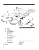
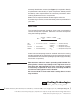
Fan Components 122 121 150 ft·lbƒ (204 N·m) 101 HUB ASSEMBLY IDENTIFICATION NUMBER 123 300 SEE FIG 6 FOR DETAILS 15 ft·lbƒ (20 N·m) 140 OUTBOARD ROW NOT REQD ON 30" DIA.
Fan Hub Installation The following instructions detail the process for installing a Marley HP7000 Fan on a Marley Geareducer® with a tapered fan (output) shaft and bolted fan hub retention. Installation on other gear reduction units may be different. Contact your Marley sales representative for supplemental instructions if required. 1–Remove the retention plate and hardware from the top of the Geareducer shaft.
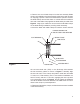
Fan Blade Installation Marley HP7000 fan blades are manufactured to equal moment weight and blade clamps to equal static weight. The blades and clamps can be installed in any position without affecting fan balance. Note At the end of the blade shank on a nameplate is inscribed a letter code (i.e. “A” or “B” etc.). When installing or replacing blades use only blades with the same letter code.
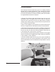
2–Remove one set of blade clamps from the hub assembly. Blade clamps are installed on the hub assembly at the factory with spacers for shipping purposes. Remove and discard the spacers. Position the blade clamps around the shank of a blade with the machinedface end of the blade clamp against the blade safety shoulder. See Figure 5. Large nylon cable ties can be used to hold blade clamps on the blade during installation providing easier assembly.
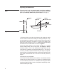
Adjusting Fan Blade Pitch Note The trial pitch is the calculated setting for design conditions (water rate , heat load, air density, and brake horsepower). The trial pitch is provided by SPX Cooling Technologies (see page 2). BLADE TIP STRAIGHT EDGE BEVEL PROTRACTOR PITCH ANGLE Figure 6 2" Section 1–Select a position on the fan circumference and rotate each blade to this common location when setting or checking blade pitch.
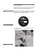
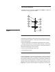
Hub Cover Installation Install the hub cover as shown in Figure 1 and Figure 7. Tighten all hex nuts to 15 ft·lbƒ (20 N·m) torque. 145 300 142 142 144 143 146 102 142 141 Figure 7 Fan Maintenance Preventative maintenance will prolong useful life and assure continued trouble-free operation. After the first week and subsequently at six month intervals: • Torque all hardware to specifications referenced in this manual.
assembly identification number (see Figure 1) is required to identify a replacement hub assembly or repair components. Please provide the Marley sales representative the necessary information when ordering replacement fans or components. Blades can be replaced without rebalancing the entire fan. If rebalancing is desired, contact the Marley sales representative in your area. Motor Load The corrected horsepower should be close to but not exceed the contract horsepower specified.