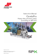
Instruction Manual CombiPro Heavy duty process pump according to API 610 Orginal instructions Read and understand this manual prior to operating or servicing this product. CR/EN (1004) 4.
EC Declaration of conformity (Directive 2006/42/EC, appendix II-A) Manufacturer SPX Process Equipment NL B.V. Dr. A.F.
2 EC/EN (1001) 5.
CombiPro Instruction manual CombiPro All technical and technological information in this manual as well as possible drawings made available by us remain our property and shall not be used (otherwise than for the operation of this pump), copied, duplicated, made available to or brought to the notice of third parties without our prior written consent. SPX Process Equipment NL B.V. (hereafter called Johnson Pump) is part of SPX Process Equipment AB.
4 CR/EN (1004) 4.
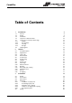
CombiPro Table of Contents 1 1.1 1.2 1.3 1.4 1.5 1.5.1 1.5.2 1.5.3 1.5.4 1.6 2 2.1 2.2 2.3 2.4 2.5 2.6 2.7 2.8 2.9 2.10 2.11 2.12 2.13 2.14 2.15 3 3.1 3.2 3.3 3.4 3.4.1 3.4.2 3.4.3 3.4.4 3.4.5 3.5 CR/EN (1004) 4.
3.6 3.7 4 4.1 4.2 4.3 4.4 4.5 4.6 4.7 4.8 5 5.1 5.2 5.3 5.4 5.5 5.6 Commissioning Inspection of the pump Inspection of the motor Pumps with oil-bath lubricated bearings Preparing the pump unit for commissioning Checking the sense of rotation Start-up Pump in operation Noise Maintenance Daily maintenance Mechanical seal Lubrication of the bearings Environmental influences Noise Faults 23 23 25 25 25 25 26 26 26 26 26 27 27 27 27 28 28 28 6 Problem solving 29 7 Disassembly and assembly 31 7.1 7.2 7.
CombiPro 9 9.1 9.1.1 9.1.2 9.2 9.2.1 9.2.2 9.3 9.3.1 9.3.2 9.4 9.4.1 9.4.2 9.5 9.5.1 9.5.2 9.6 9.6.1 9.6.2 10 10.1 10.1.1 10.1.2 10.1.3 10.2 10.2.1 10.2.2 10.3 10.3.1 10.3.2 10.4 10.4.1 10.4.2 10.5 10.5.1 10.5.2 CR/EN (1004) 4.
8 CR/EN (1004) 4.
CombiPro 1 Introduction 1.1 Preface This manual is intended for technicians and maintenance staff and for those who are in charge of ordering spare parts. This manual contains important and useful information for the proper operation and maintenance of this pump. It also contains important instructions to prevent potential accidents and damage, and to ensure safe and fault-free operation of this pump.
1.3 Guarantee Johnson Pump shall not be bound to any guarantee other than the guarantee accepted by Johnson Pump. In particular, Johnson Pump will not assume any liability for explicit and/or implicit guarantees such as but not limited to the marketability and/or suitability of the products supplied. The guarantee will be cancelled immediately and legally if: • Service and/or maintenance is not undertaken in strict accordance with the instructions.
CombiPro 1.5.3 Hoisting When hoisting a pump or complete pump units the straps must be fixed in accordance with figure 1 and figure 2. ! 1.5.
1.6 Ordering parts This manual contains a survey of the spare parts recommended by Johnson Pump as well as the instructions for ordering them. A fax-order form is included in this manual. You should always state all data stamped on the type plate when ordering parts and in any other correspondence regarding the pump. ➢ This data is also printed on the label on the front of this manual.
CombiPro 2 General 2.1 Pump description The CombiPro represents a range of horizontal "heavy duty" centrifugal pumps. The design of this range of pumps is based on the guidelines for: "Centrifugal Pumps for Petroleum, Petrochemical and Natural Gas Industries" from the "American Petroleum Institute" otherwise known as the API Standard 610 (identical to ISO 13709). The CombiPro range therefore meets the high requirements which have been set by the refineries and the petrochemical industry.
2.3 Type code Pumps are available in various designs. The main characteristics of the pump are shown in the type code. Example: CR 50A-200 A-8 1CW-FX Pump family CR CombiPro 50A 200 Pump size discharge connection [mm].
CombiPro 2.4 Serial number Serial number of the pump or pump unit are shown on the name plate off the pump and on the label on the cover of this manual. Example: 01-1000675A 01 100067 5 A B 2.5 year of manufacture unique number number of pumps pump with motor pump with free shaft end Construction The pump has a modular design. The main components are: • Pump casing • Impeller • Shaft sealing • Bearing In general for each individual pump type there is only one design of the pump casing and the impeller.
2.7 Impeller The back of the closed impeller is provided with back vanes in order to limit the pressure on the shaft seal and to allow the flushing liquid to circulate. Contamination of the shaft seal is also prevented. On the inlet side the impeller is provided with an interchangeable wear ring. Running clearances meet the requirements of API 610. 2.8 Pump cover The pump is designed to fit any seal type in accordance with API 682.
CombiPro 2.13 Application area The application area globally looks as follows:, Table 1: Application area. Maximum value 350 m3/h 160 m 3500kPa (35 bar) -30 to +350 °C Capacity Discharge head System pressure Temperature 300 mm2/s Viscosity However, the maximum allowable pressures and temperatures depend strongly on the selected materials and components. Also working conditions may cause differences. 2.
18 General CR/EN (1004) 4.
CombiPro 3 Installation 3.1 Safety • Read this manual carefully prior to installation and commissioning. Non-observance of these instructions can result in serious damage to the pump and this will not be covered under the terms of our guarantee. Follow the instructions given step by step. • Ensure that the pump can not be started if work has to be undertaken to the pump during installation and the rotating parts are insufficiently guarded.
3.4 Mounting 3.4.1 Installation of a pump unit Pump and motor shafts of complete pump units are adjusted perfectly in line in the works. 1 Horizontal alignment of the base plate is done with levelling screws. Use a spirit level for correct horizontal alignment of the base plate. 2 Grout the base plate, see paragraph 3.4.5 "Grouting base plate". 3 Check the alignment of pump and motor shafts and if necessary realign, see paragraph 3.4.3 "Alignment of the coupling". 3.4.
CombiPro Parallel alignment 1 Mount dial gauge (A) on the coupling halve motor side, see figure 3. 2 Make index lines on the two coupling halves. 3 Set the dial gauge pointer to zero, turn motor shaft 360 °. 4 Read dial gauge (A). Add or remove shims under the motor until the reading of the dial gauge is within the allowable tolerance, see paragraph 3.4.4 "Tolerances for aligning the coupling". 5 Repeat the procedure. 6 Remove dial gauge (A).
5 When the grout has thoroughly hardened, check the base plate bolt nuts and tighten if necessary. 1 5 2 5 3 1 Drain pan. 2 Wooden frame. 4 3 Shims. 4 Basic foundation. 5 Grout. Figure 4: 3.5 Grouting base plate. Piping • The piping to the suction and delivery connections must fit exactly and must not be subject to stress during operation. For the maximum allowable forces and moments on the pump flanges see paragraph 10.2 "Permissible forces and moments on the flanges".
CombiPro • Sudden changes in the rate of flow can lead to high pressure impulses in the pump and the piping (water shock). Therefore, do not use quick-acting closing devices, valves etc. 3.6 Accessories • Fit any parts that may have been supplied separately. • If the liquid does not flow towards the pump, fit a foot valve at the bottom of the suction pipe. If necessary, combine this foot valve with a suction strainer to prevent impurities from being drawn in.
24 Installation CR/EN (1004) 4.
CombiPro 4 Commissioning 4.1 Inspection of the pump Check whether the pump shaft turns freely. Do this by turning the shaft end at the coupling a few times by hand. 4.2 Inspection of the motor Check whether the fuses have been mounted. 4.3 ! Pumps with oil-bath lubricated bearings Pumps provided with oil-bath lubricated bearings are shipped without oil and must be filled with oil prior to commissioning the pump! For the specification of the oil to be used, see paragraph 10.3 "Lubricants".
4.4 Preparing the pump unit for commissioning Proceed as follows, both when the unit is put into operation for the first time and after the pump has been overhauled. 1 Fully open the stop valve in the suction pipe. Close the delivery stop valve. 2 Fill the pump and the suction pipe with the liquid to be pumped. 3 Turn the pump shaft a few times by hand and add more liquid, if necessary. 4.
CombiPro 5 Maintenance 5.1 Daily maintenance • Regularly check the oil level, see figure 7. Figure 7: 5.2 Oil level indication. No water should get into the terminal box of the electric motor when the pump room is sprayed clean! Never spray water on hot pump parts! The sudden cooling down may cause them to burst and hot water may flow out! Mechanical seal A mechanical seal generally requires no maintenance, however, it should never be allowed to run dry.
5.4 Environmental influences • Regularly clean the filter in the suction pipe or the suction strainer at the bottom of the suction pipe, as the inlet pressure may become too low if the filter or the suction strainer is fouled. • If there is a risk that the pumped liquid expands during solidification or freezing, the pump has to be drained and, if necessary, flushed after it has been put out of service. • If the pump is out of service for a long time, it has to be preserved. 5.
CombiPro 6 Problem solving Faults in a pump installation can have various causes. The fault may not be in the pump, it may also be caused by the pipe system or the operating conditions. Firstly, always check that installation has been executed in accordance with the instructions in this manual and that the operating conditions still correspond with the specifications for which the pump was purchased.
Table 4: Possible causes of pump failures.
CombiPro 7 Disassembly and assembly 7.1 Precautionary measures Take adequate measures to avoid that the motor is started while you are working on the pump. This is especially important for electric motors with remote control: • Switch the operating switch near the pump (if available) to "OFF". • Switch off the pump switch on the switchboard. • If necessary remove the fuses. • Hang a danger board near the switchboard cabinet. 7.2 Special tools Assembly and disassembly work requires no special tools.
7.4 Back-Pull-Out system The pumps are designed with a Back-Pull-Out system. The pump unit is designed with a spacer-coupling, the spacer of this coupling can easily be removed. After that the bearing bracket with the entire rotating part can be removed. This means that almost the whole pump can be dismantled without having to detach the suction and delivery piping. The motor remains in its position. 7.4.1 Disassembling the guard 1 Loosen bolts (0237) and remove these. See figure 9.
CombiPro 7.4.4 Assembling the guard 1 Place the guard (0270) on the coupling. 2 Fit the guard with bolts (0237). 0270 0237 Figure 9: 7.5 Fitting the guard. Replacing the impeller and the wear ring If the play has risen to 0,9 mm or greater due to wear then both wear rings are replaced. 7.5.1 Disassembling the impeller 1 Remove the Back-Pull-Out unit, see paragraph 7.4.2 "Disassembling the Back-PullOut unit". 2 Unlock the set screw (1825) and remove the cap nut (1820).
7.5.3 Disassembling the wear rings After removing the Back-Pull-Out unit (see paragraph 7.4.2 "Disassembling the BackPull-Out unit") the wear rings can be removed. In most cases the ring has been fixed so tightly that it cannot be removed undamaged. d b d b A B C D Figure 10: Removal of wear ring. 1 Disassembling the impeller, see paragraph 7.5.1 "Disassembling the impeller" 2 Unlock the set screw (0155) that lock up the impeller wear ring (0150) on the impeller.
CombiPro 7.5.4 Assembling the wear rings 1 Clean and degrease the fitting edge of the pump casing and impeller where the wear ring is to be mounted. 2 Fit the casing wear ring in the pump casing. Take care it is not pushed out of alignment! 3 Fit the impeller wear ring on the impeller. Take care it is not pushed out of alignment! ! Make sure that they are not inserted obliquely! 4 Both wear rings then have to be secured. Drill 3 holes Ø5 mm, 9 mm deep, right on the seam between impeller and wear ring c.
7.6 Mechanical seal 7.6.1 Instructions for mounting a cartridge seal ➢ First read the following instructions regarding mounting a cartridge seal. Follow these instructions closely when mounting a cartridge seal. • This mechanical seal comes as a ’full cartridge seal’. This means that this mechanical seal must be mounted as one single piece and that it shall NOT be taken apart! • A cartridge seal is a fragile precision instrument.
CombiPro 7.7 Bearing 7.7.1 Instructions for assembly and disassembly of bearings ➢ First read the following instructions regarding assembly and disassembly. Follow these instructions closely when assembling and disassembling bearings. Disassembly: • Use a proper puller to remove the bearings from the pump shaft. • If no proper puller is available, carefully knock at the inner raceway of the bearing. Use an ordinary hammer and a mild steel drift for this.
7.7.3 Assembling bearing 1 Clean the interior of the bearing bracket properly. 2 Preheat the angular contact ball bearings and the inner ring of the cylindrical roller bearing and fit them onto the pump shaft. Make sure they are positioned straight on the pump shaft and push them firmly against the shaft shoulder. The cylindrical roller bearing (2250) is fitted at the impeller side. The angular contact ball bearings are fitted in O-position at the drive side.
CombiPro 8 Dimensions 8.1 Pump dimensions DN2 ajx ∅ al af ad zc zb DN1 ag DN2 ea mg eb h9 vd zd ∅ db ed vj 14 10 BE BN DN3 ga gm ec BM BD zn gix ∅ gk DN3 DN1 gg gc ∅ vf BV an am aix ∅ ak ac aa ae ab ah tb vi vk vv vb vc ve va zl Figure 12: Pump dimensions. Connections BM BV Oil drain Oil filling plug ½ BSP ½ NPT Connections (optional) BD BE BN CR/EN (1004) 4.
8.2 Flange dimensions 8.2.1 Flange dimensions ASME B16.5 150lbs (ISO7005 PN20) aa 50 (2") 80 (3") 100 (4") 150 (6") 200 (8") ab 40 (1½") 50 (2") 80 (3") 100 (4") 150 (6") ga 15,8 (½") 20,9 (¾") 8.2.2 gc 34,9 42,9 DN3 ge gg 60,3 90 69,9 100 gixgk 4x15,9 4x15,9 ag 165 210 254 318 381 ah aixak ajxal am an 156 4x18 4x16 22 21 165 4x18 4x18 29 22 210 8x18 4x18 32 29 254 8x22 8x18 37 32 318 8x22 8x22 41 37 gm 11,2 12,7 Flange dimensions ASME B16.
CombiPro 8.
42 Dimensions CR/EN (1004) 4.
CombiPro 9 Parts 9.1 Ordering parts 9.1.1 Order form You can use the order form included in this manual for ordering parts. When ordering parts always quote the following data: 1 Your address. 2 The quantity, the item number and the description of the part. 3 The pump number. The pump number is stated on the label on the cover of this manual and on the type plate of the pump. 4 In the event of different electric motor voltage you should state the correct voltage. 9.1.
9.2 Pump 9.2.1 Sectional drawing pump 2420/2425 2145 2135 0805 0810 0800 0855 0850 0820 0130 0135 2190 2830 2820 0150 0155 2810 1825 1820 2815 2140 0276 0235 0236 0239 2130 2400/2405 2410/2415 2210 2200 2100 0140 2150 2155 1860 0100 0110 0120 1920 1930 1905 1900 1805 0300 2220 1915 1800 1810 2190 2300 2260 2160 2115 2570 2180 1950 2160 2110 2120 2560 2125 2250 Figure 13: 44 Sectional drawing pump. Parts CR/EN (1004) 4.
CombiPro 9.2.
Item 2190 22003) 22103) 2220 Quantity Description 2**** 1 set screw pump shaft 22502)3) 1 1 1 22602)3) 2 2300 2400 2405 2410 2415 2420 2425 25603) 1 1 2 1 2 1 2 1 coupling key deflector cylindrical roller bearing angular contact ball bearing inner circlip name plate rivet arrow plate rivet oil level plate rivet lock nut 25703) 2810 2815 2820 2830 1 4 4 2 2 locking washer Allen screw Allen screw Allen screw washer API-610 Material Classes S-8 C-6 A-8 stainless steel stainless steel chrome steel
CombiPro 9.3 Mechanical seal piping plan 11 - tubing 9.3.1 Drawing plan 11 - tubing 1410 1400 1420 1460 1504 1430 Figure 14: 9.3.2 Drawing plan 11 - tubing. Parts list plan 11 - tubing API-610 Material Classes Item Quantity Description 1400 1410 1420 1430 1460 1504 CR/EN (1004) 4.
9.4 Mechanical seal piping plan 11 - flanged 9.4.1 Drawing plan 11 - flanged 2015 2060 2020 2030 2050 2035 2060 2040 2035 2080 2010 Figure 15: 9.4.2 Item 48 2070 2050 2025 2030 2000 Drawing plan 11 - flanged.
CombiPro 9.5 Oil chamber jacket 9.5.1 Drawing oil chamber jacket 0340 2860 0340 0330 2845 2840 2850 Figure 16: 9.5.2 Item Drawing oil chamber jacket. Parts list oil chamber jacket 0330 0340 2840 2845 2850 1 2 6 6 1 plug plug bolt washer oil chamber jacket 28601)2)3) 1 gasket CR/EN (1004) 4.
9.6 Pump casing jacket 9.6.1 Drawing pump casing jacket 0100 Figure 17: 9.6.2 Drawing pump casing jacket. Parts list pump casing jacket Item Quantity Description 0100 50 1 pump casing jacket Parts API-610 Material Classes S-1 S-6 S-8 carbon steel C-6 A-8 stainless steel CR/EN (1004) 4.
CombiPro 10 Technical data 10.1 Tightening moments 10.1.1 Tightening moments for bolts and nuts ! For nuts for pump casing (item 0810), see paragraph 10.1.3 "Torques settings for nuts for pump casing"! Table 5: Tightening moments for bolts and nuts. Materials Thread M6 M8 M10 M12 M16 10.1.2 A2, A4 Tightening moments for cap nut Table 6: Tightening moments for cap nut (1820). Size M12 M16 M24 CR/EN (1004) 4.0 8.
10.1.
CombiPro 10.2 Permissible forces and moments on the flanges Forces and moments acting on the pump flanges due to pipe loads can cause misalignment of the pump and driver shafts, deformation and overstressing of the pump casing, or overstressing of the fixing bolts between the pump and the base plate. Z Y X Z Y X Z Figure 18: CR/EN (1004) 4.0 Y X Coordinate system.
10.2.
CombiPro 10.2.2 Allowable forces and moments on the drain flange Table 9: According API 610 - table 4 "Nozzle loadings" Allowable forces [N] Fx Fy 890 710 Fz Allowable moments [Nm] Fr 580 1280 Mx My Mz Mr 460 230 350 620 Pump mounted on a grouted base plate of carbon steel Fr, Mr = resultant 10.3 Lubricants 10.3.1 Oil Table 10: Recommended oils according to ISO VG 68 classification for ambient temperatures above 15 °C. BP CHEVRON CHEVRON EXXONMOBIL EXXONMOBIL SHELL TOTAL 10.3.
56 10.4 Hydraulic performance 10.4.1 Performance overview cast steel material class S-1 Figure 19: Performance overview 3000 min-1. Figure 20: Performance overview 1500 min-1. Technical data CR/EN (1004) 4.
CombiPro CR/EN (1004) 4.0 Figure 21: Performance overview 3600 min-1. Figure 22: Performance overview 1800 min-1.
10.4.2 58 Performance overview material classes S-6, S-8, C-6, A-8 Figure 23: Performance overview 3000 min-1. Figure 24: Performance overview 1500 min-1. Technical data CR/EN (1004) 4.
CombiPro CR/EN (1004) 4.0 Figure 25: Performance overview 3600 min-1. Figure 26: Performance overview 1800 min-1.
10.5 Noise data 10.5.1 Pump noise as a function of pump power [dB(A)] 4103_A 98 96 94 92 90 88 86 84 82 80 78 76 74 72 70 68 66 64 62 60 58 56 54 A B 0,1 Figure 27: 10 P [kW] 200 100 Noise level as function of pump power [kW] at 1450 min-1 A = sound energy, B = sound pressure. [dB(A)] 4104_A 100 1 95 A 90 85 B 80 75 70 65 60 0,1 Figure 28: 60 1 10 P [kW] 100 300 Noise level as function of pump power [kW] at 2900 min-1 A = sound energy, B = sound pressure.
CombiPro Noise level of entire pump unit 3,2 3,0 2,8 2,6 2,4 2,2 2,0 1,8 1,6 1,4 1,2 1,0 0,8 0,6 0,4 0,2 0,0 L [dB] 4102 10.5.2 0 1 Figure 29: 2 3 4 5 6 7 8 9 10 11 12 13 14 15 16 17 18 19 20 |L1 - L2| [dB] Noise level of entire pump unit. In order to determine the total noise level of the entire pump unit, the noise level of the motor must be added to that of the pump. This can be easily done by using the graph above. 1 Determine the noise level (L1) of the pump, see figure 27 or figure 28.
62 Technical data CR/EN (1004) 4.
CombiPro Index A Accessories . . . . . . . . . . . . . . . . . . . . . . . . .23 Application area . . . . . . . . . . . . . . . . . . . . .17 Applications . . . . . . . . . . . . . . . . . . . . . . . . .13 B Back-Pull-Out unit assembling . . . . . . . . . . . . . . . . . . . . . .32 disassembly . . . . . . . . . . . . . . . . . . . . .32 Base plate . . . . . . . . . . . . . . . . . . . . . . . . . .16 Bearing . . . . . . . . . . . . . . . . . . . . . . . . . . . .37 assembly . . . . . . . . . . . . . . .
Monitoring . . . . . . . . . . . . . . . . . . . . . . . . . .26 N Noise . . . . . . . . . . . . . . . . . . . . . . . . . . 26, 28 O Oil contents . . . . . . . . . . . . . . . . . . . . . . . . .55 P Pallets . . . . . . . . . . . . . . . . . . . . . . . . . . . . .10 Performance overview . . . . . . . . . . . . . . . .56 Permissible forces . . . . . . . . . . . . . . . . . . .53 Piping . . . . . . . . . . . . . . . . . . . . . . . . . . . . . .22 Precautionary measures . . . . . . . . . . . . . . .
Order form for spare parts FAX Nr. ADDRESS Your order will only be dealt with if this order form has been correctly completed and signed. Order date: Your order number: Pump type: Execution: Quantity Item. No. Part Article number pump Delivery address: Ordered by: ORDFORM (0804) 3.
66 ORDFORM (0804) 3.
Your local contact: SPX Process Equipment NL B.V. Dr. A. F. Philipsweg 51, 9403 AD Assen, THE NETHERLANDS P.O. Box 9, 9400 AA Assen, THE NETHERLANDS Phone: + 31 (0) 592 37 67 67 Fax: + 31 (0) 592 37 67 60 E-Mail: johnson-pump.nl@processequipment.spx.com For more information about our worldwide locations, approvals, certifications, and local representatives, please visit www.johnson-pump.com / www.spxpe.com.