/ Marley Ultra Low-Noise Fan / User Manual 07-1126
Contents General Information....................................................................... 4 Installation..................................................................................... 5 Operation..................................................................................... 11 Maintenance............................................................................... 13 Parts List..................................................................................... 16 Trouble Shooting..
General Information Description The Marley Ultra Low-Noise series of fans represent the top in the new generation of super low noise fans—the FRP blades have been developed to meet the most stringent noise limitations. The fans permit variable pitch adjustment at standstill and feature a simplified design. Each blade is fixed to the hub with two bolted aluminum pillow blocks. Balancing When the rotor is dispatched in assembled form, each unit is dynamically balanced within a degree of G = 6.
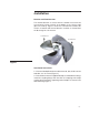
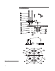
Installation Rotation and Flow Direction The rotation direction is correct when the airflow moves from the convex back (suction surface) of the blade, to the concave side (pressure surface). Figure 1 shows the conventional clockwise direction of rotation and normal direction of airflow as viewed from the discharge face of the rotor. Flow Direction Flow Direction Figure 1 Installation Instructions 1––Remove blade pillow block and fasteners 4, 5, 6, 7, 15 from the hub disk, one set a time (Figure 2).
Installation 10B 9 10A 3 7 5 1 2 Figure 2 8 6 4 6 10
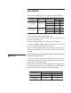
Installation Torque hub assembly bolts 11 according to the following table: Fan Diameter Flange Type inches 84" to 96" 108" to 168" Type 115 Type 190 Bolt Type Bolt Torque N·m ft·lb M16 cl. 8.8 230 169 M16 cl. A4-70 126 93 M16 cl. A4-80 168 124 M20 cl. 8.8 447 329 M20 cl. A4-70 246 181 M20 cl. A4-80 328 241 3––Hub into driveshaft installation (Figure 2). • As for the hub with cylindrical bore, the hub is bored to attach directly to the drive shaft.
Installation Caution Warning The drive shaft end must remain recessed at least 1⁄32" in the hub bore to prevent dangerous rotor vertical translation once retaining bolt 16 has been tightened to the shaft end. Never power the drive shaft with bushing bolts not torqued or bushing improperly positioned. 4––Install the blade. Sandwich the blade shank between the pillow blocks 4 and 5, ensuring both the pins 7 are in proper position (Figure 2).
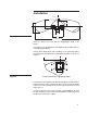
Installation G X øH R T Z V S K D U øF øE øC Figure 3 FAN DIAMTER (A) Rotate the blade on its axis until the required pitch angle is obtained. Check there is no gap between each blade shaft shoulder and corresponding pillow block. Torque pillow block bolts 15 according to the following tables, complying with bolt orientation and tightening order as shown in Figure 4. Figure 4 1 3 4 2 4 Bolt Pillow Block Tightening Order 6––Repeat for each blade steps described in points 4 and 5.
Installation Fan Diameter inches Note Bolt 15 Bolt Torque N·m ft·lb 84" to 96" M18 282.5 208 108" to 120" M20 400.3 294 132" to 144" M24 679.8 500 The screw class information is shown in the fan documentation part list. Stainless steel bolts 15 with the A4-80 stamping: Fan Diameter inches Note 10 Bolt 15 Bolt Torque N·m ft·lb 84" to 96" M18 175.6 129 108" to 120" M20 246.2 181 132" to 144" M24 425.
Operation Prior to Start-Up 1––Make sure all the pillow blocks are fixed to the hub boss—if any movement of the blocks is detected, do not operate the fan and check the torque of bolts 15. 2––Rotate fan to check tip clearance is in accordance with the specified value (tip clearance ratio x/D, where x = the distance from the blade tip to the fan ring and D = the rotor diameter). The gap between blade tip and fan ring must be measured along blade axis.
Operation Figure 5 3––After the rotor has been running for one hour, check the torque of the hub screws 15. 4––Repeat the check of screws 15 after 24 hours from start-up.
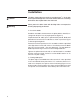
Maintenance Maintenance and Operation 1––Inspect the overall fan condition periodically. Inspection intervals depend on fan operating conditions and may vary from a minimum of 2 weeks to a maximum of 6 months. The following components should be specifically inspected when inspecting the overall fan conditions: - Screw torque. - Fasteners corrosion. - General condition of blade surface. 2––Ice formation on the blades of operating fans must be strictly avoided.
Maintenance Possible Causes of Vibration The actual causes of vibration may change considerably. Some of the most common are as follows. 1–– Unbalance of one or more blades: the vibration caused by blade imbalance occurs on the tip path plane with a frequency equal to the fan RPM and at an amplitude which is dependent on the degree of imbalance and the square of the rotational speed. 2––Blade pitch angle not included in the ± 0.
Maintenance 9––Worn output shaft bearing: this condition generates vibration on the tip path plane at a frequency equal to the rotor RPM. 10––The fan and/of the structure bolts are not tightened: in this case all the bolts have to be tightened. 11––The draining holes of the blades are obstructed: they have to be opened. Note The amplitude of the fan vibrations is determined by the rigidity of its support.
Parts List Item 16 Standard Protection 1 Blade FRP –– 2 Coupling Flange Steel Epoxy Paint 3 Hub Disk Steel Epoxy Paint 4 Lower Pillow Block Aluminum –– 5 Upper Pillow Block Aluminum –– 6 Pillow Block Plate Steel Epoxy Paint 7 Pins Steel Zinc Plated 8 Coupling Flange Washer Steel - R40 HDG 9 Coupling Flange Lock Washer Steel - R40 HDG 10 Note Standard Material Description Figure 6 Coupling Flange Nut Steel - 8.
Parts List 11 8 15 12 6 2 5 1 16 17 16 4 7 3 12 13 14 8 9 10 Figure 6 10B 10A 17
Troubleshooting Trouble Cause Remedy System congestion. Clean the entire system. Check the real obstacles area and the inlet shape towards the original design. Obstacles to the air flow. In dry-coolers the minimum free height of the inlet area has to be 1 time the fan diameter at least; this height has to be higher in case of multiple units in line. Static pressure higher than the specified one. Increase blade pitch angle (till 3º after checking the data sheet selection.
7401 WEST 129 STREET | OVERLAND PARK, KANSAS 66213 UNITED STATES | 913 664 7400 | spxcooling@spx.com | spxcooling.com In the interest of technological progress, all products are subject to design and/or material change without notice. ©2009 SPX Cooling Technologies, Inc.