○ ○ ○ ○ ○ ○ ○ ○ ○ ○ ○ ○ ○ ○ ○ ○ ○ ○ ○ ○ ○ ○ ○ ○ ○ ○ ○ ○ ○ ○ ○ ○ ○ ○ ○ ○ ○ ○ ○ ○ ○ ○ ○ ○ ○ ○ ○ ○ ○ ○ ○ ○ ○ ○ ○ ○ ○ ○ ○ ○ ○ ○ ○ ○ ○ ○ ○ ○ ○ ○ ○ ○ ○ ○ ○ ○ ○ ○ Operating Manual Model 34700-2K/17700-2K Recovery/Recycling/Recharging Unit
Model 17700-2K (for R-12 refrigerant) Model 34700-2K (for R-134a refrigerant) Recover, Recycle, and Recharge Unit SAFETY DEFINITIONS: Follow all WARNING, CAUTION, IMPORTANT, and NOTE messages in this manual. These messages are defined as follows: WARNING means you may risk serious personal injury or death; CAUTION means you may risk personal injury, property damage, or unit damage; IMPORTANT means you may risk unit damage; and NOTEs provide clarity and helpful tips.
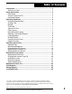
Table of Contents Introduction .............................................................................................. 2 Glossary of Terms ................................................................................. 2 Setup Instructions .................................................................................... 2 Initial Setup ............................................................................................. 4 Vacuum Pump Initial Fill .........................................
Introduction This manual contains important safety procedures concerning the operation, use, and maintenance of this product. Failure to follow the instructions contained in this manual may result in serious injury. If you are unable to understand any of the contents of this manual, please bring it to the attention of your supervisor. Do not operate this equipment unless you have read and understood the contents of this manual.
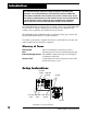
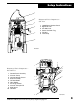
Setup Instructions 1 2 Diagram of Unit’s Components— Side View 3 1. 2. 3. 4. 5. 6.
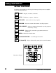
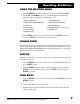
Setup Instructions KEYPAD FUNCTIONS In addition to the number keys, the keypad contains special keys that accomplish specific operating functions. START START— Begins, or resumes, a function. STOP STOP— Terminates, or pauses, a function. RECOVER RECOVER— Activates the recovery sequence. VACUUM VACUUM— Activates vacuum and automatic recycling sequence. VAC-CHARGE CHARGE MENU VAC-CHARGE— Activates vacuum and automatic recycling sequence, followed by a charge.
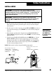
Setup Instructions INITIAL SETUP CAUTION! R-134a systems have special fittings (per SAE specifications) to avoid cross-contamination with R-12 systems. Do not attempt to adapt your unit for another refrigerant — system failure will result! Read and follow all warnings at the beginning of this manual before operating the unit. CAUTION! Avoid the use of an extension cord, because the extension cord may overheat. However, if you must use an extension cord, use a No.
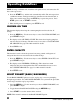
Setup Instructions NOTE: The vacuum pump is shipped without oil in the reservoir. Before starting the pump, oil must be added to the pump, or damage to the pump may occur. IMPORTANT! For maximum performance, change the vacuum pump oil frequently. 5. Press the START key to begin the oil fill process. 6. Attach the flexible tube and cap to the oil bottle, and pour eight ounces of vacuum pump oil into the fill port. 7. Press the START key.
Operating Guidelines USING THE SELECTION MENU 1. Press the MENU button. The top line of the display reads SETUP MENU. 2. Use the UP and DOWN arrow keys to scroll through the menu choices displayed on the second line. The menu choices are: 1. SELECT LANGUAGE 7. VACUUM OIL TIME 2. SELECT UNITS (ENGLISH/METRIC) 8. CHANGE VACUUM PUMP OIL 3. TANK REFILL 9. SELECT PROMPTS 4. RECYCLE ONLY 10. CHANGE DEFAULTS (password protected) 5. FILTER CAPACITY 11. VERSION X.XX 6. CHANGE FILTER 3.
Operating Guidelines NOTE: If using a refillable tank, install the tank upside down, and connect the fill hose to the vapor valve. 4. Press the START key, and the tank automatically refills. The unit stops when a sufficient amount of refrigerant has been transferred to the internal tank, or if the source tank is empty. Press the STOP key to pause the process. Press STOP again to exit, or START to resume. 5. When the fill process is complete, press STOP to exit.
Operating Guidelines SELECTING A UNIT (METRIC/ENGLISH) 1. Press the MENU key. Use the arrow keys to choose SELECT UNITS, and press START to begin. 2. Toggle between UNITS ENGLISH and UNITS METRIC using the arrow key. 3. Press START to save the current choice and exit. LANGUAGE SELECT The operator can choose between English, Spanish, French, Italian, or German. 1. Press the MENU key. Use the arrow keys to choose SELECT LANGUAGE, and press START to begin. 2.
Operating Guidelines USING THE CONTROL PANEL The control panel has various components that control specific operating functions. MAIN POWER SWITCH—Supplies electrical power to the control panel. DIGITAL DISPLAY—Used on the visual interface between the operator and the machine. LOW SIDE MANIFOLD GAUGE—Connects to an A/C system and shows the system’s low side pressure. HIGH SIDE MANIFOLD GAUGE—Connects to an A/C system and shows the system’s high side pressure.
Operating Instructions OPERATING TIPS Follow the SAE-J1991 recommended service procedure for the containment of R-12, and the SAE-J2210 recommended service procedure for the containment of R-134a. The recovery compressor is not a vacuum pump. The compressor pulls the A/C system to a partial vacuum only. You must use the unit’s vacuum cycle to remove moisture from the A/C system. We recommend a minimum 15-minute vacuum, or follow the system manufacturer's recommendations.
Operating Instructions RECOVERING REFRIGERANT WARNING Wear safety goggles when working with refrigerant. Read and follow all warnings at the beginning of this manual before operating the unit. 1. Connect the power cord to the back of the unit, and plug it into the correct voltage outlet. 2. Turn on the MAIN POWER and, if necessary, empty the oil drain bottle located on the right hand side of the unit. 3. Press the RECOVER button. 4.
Operating Instructions 9. When the system has recovered to a vacuum level of approximately 13 in. Hg., the compressor automatically shuts off. 10. The unit then goes into automatic oil drain, and the display reads: OIL DRAINING. Oil draining can require up to 90 seconds to complete. 11. After the oil drain is complete, the display alternates between: RECOVERY COMPLETE RECOVERED XX.XX lbs. (X.XX kg) CHECK OIL BOTTLE RECOVERED XX.XX lbs. (X.
Operating Instructions EVACUATING THE A/C SYSTEM WARNING IMPORTANT! Evacuate the system for at least 15 minutes to ensure adequate moisture and contaminant removal. Wear safety goggles when working with refrigerant. Use only authorized refillable refrigerant tanks. Read and follow all warnings at the beginning of this manual before operating the unit. In addition to the number keys, the keypad contains special keys that accomplish specific operating functions.
Operating Instructions NOTE: It is not necessary to change the High side panel valve from vacuum to charge when performing the VAC-CHARGE function. 3. Press the START key to charge the default amount of refrigerant, or use the number keys to enter the desired charge weight. Then press the START key. 4. If the weight entered leaves less than 3 lbs (1.36 kg) of refrigerant in the internal storage vessel, the VAC-CHARGE process does not begin, and the display reads INSUFFICIENT REFRIG.
Operating Instructions REPLENISHING A/C SYSTEM OIL CAUTION! To prevent air from entering the A/C system, never let the oil level drop below the pickup tube while charging or replenishing. Before charging the A/C system, you must replenish any oil removed from the A/C system during the recovery process. Charge only the amount of oil that was removed from the A/C system during recovery. Check the oil drain bottle to determine the amount of oil that was removed during recovery.
Operating Instructions RECHARGING THE A/C SYSTEM WARNING Wear safety goggles when working with refrigerant. Use only authorized refillable refrigerant tanks. Disconnect hoses with extreme caution! All hoses may contain liquid refrigerant under pressure. Read and follow all warnings at the beginning of this manual before operating the unit. 1. Press the CHARGE button. (If an oil inject has been performed, the CHARGE key does not have to be pressed.) 2. Put the Low Side Valve in the Closed position.
Operating Instructions SLOW CHARGE PROCEDURE WARNING Before starting the vehicle's engine, verify that it is in PARK or NEUTRAL, with the emergency brake ON. Never run a vehicle without adequate ventilation in the work area. CAUTION! Close the high side manifold valve before starting the vehicle A/C system. 1. Close the High Side Valve. Put the Low Side Valve in the Recover/Vacuum position. 2. Start the vehicle, and set the AC system to its maximum setting. 3. Press START.
Maintenance Instructions REPLACING THE FILTER-DRIER Order part no. 34724 for a replacement filter-drier. The filterdrier on this unit is designed to trap acid and particulates, and is formulated to remove water from the refrigerant. You must change the filter-drier to ensure adequate moisture and contaminant removal. Typically, you can recycle up to 150 pounds (68 kilograms) of refrigerant between filter changes. CAUTION! For best results, use Robinair filterdriers (part no. 34724).
Maintenance Instructions CHANGING THE VACUUM PUMP OIL For maximum vacuum pump performance, change the vacuum pump oil after every 10 hours of operation. 1. Turn on the MAIN POWER switch. IMPORTANT! Review current local, state, and federal statutes, cases, laws, and regulations to determine the current status and appropriate disposal method for pump oil. It is the responsibility of the user to determine if a material is a hazardous waste at the time of disposal.
Maintenance Instructions 1 6 2 3 4 OPEN CLOSE 5 Diagram of Vacuum Pump 1. 2. 3. 4. 5. 6. Oil Filler Tube Pump Exhaust Oil Fill Port Sight Glass Oil Drain Fitting Inlet CHECKING FOR LEAKS Every three months, or as specified by local or state laws, you should check the unit for leaks. 1. Turn off the MAIN POWER switch, and disconnect the power cord from the outlet. 2. Open the rear door. Remove the top cover and front panel. 3. Use a leak detector to probe all connections for refrigerant leaks.
Replacement Parts List ELECTRICAL PROTECTION The unit is equipped with two circuit breakers. If either circuit breaker trips, the unit will not function correctly and may lose all power. Press the circuit breaker button to reset. The circuit breakers are on the back of the unit. GENERAL MAINTENANCE 1. On a regular basis, wipe off the unit with a clean cloth to remove grease, dust, or other dirt. 2. Periodically check the internal components for leaks—over time, fittings can loosen as the unit is moved.
Replacement Parts List 34700-2K R-134a Replacement Part Number 17700-2K R-12 Replacement Part Number 96" Red Hose 63096 68396A 96" Blue Hose 62096 68296A RA17416 RA17416 34724 34724 Compressor RA19458 RA19458 Vacuum Pump RA15425 RA15425 High Pressure Switch RA19427 RA19427 Main Power Switch RA40994 RA40994 Vacuum Switch RA18752 RA18752 Pump Protection Switch RA19429 RA19429 Automatic Expansion Valve RA19592 RA19592 Oil Catch Bottle RA17419 RA17419 Scale Assembly RA19603
Flow Diagram 1 3 INST0576 4 6 5 9 2 1. 2. 3. 4. 5. 6. 7. 14 13 12 7 11 Low Side Manifold Gauge High Side Manifold Gauge Low Side Manifold Valve High Side Coupler Oil Injector Check Valve Vacuum Pump Expansion Valve 8 8. 9. 10. 11. 12. 13. 14.
Wiring Diagram 34700-2K/17700-2K Cool-Tech Recovery/Recycling/Recharging Unit 25
Limited Warranty Robinair Limited Warranty Statement Rev. July 11, 2003 This product is warranted to be free from defects in workmanship, materials, and components for a period of one year from date of purchase. All parts and labor required to repair defective products covered under the warranty will be at no charge. The following restrictions apply: 1. The limited warranty applies to the original purchaser only. 2.
Notes 34700-2K/17700-2K Cool-Tech Recovery/Recycling/Recharging Unit 27
Notes 28 © 2001 Robinair, SPX Corporation
CONVERSION TABLE OZ. LBS. 0.5 1.0 1.5 2.0 2.5 3.0 3.5 4.0 4.5 5.0 5.5 6.0 6.5 7.0 7.5 8.0 8.5 9.0 9.5 10.0 10.5 11.0 11.5 12.0 12.5 13.0 13.5 14.0 14.5 15.0 15.5 16.0 0.03 0.06 0.09 0.13 0.16 0.19 0.22 0.25 0.28 0.31 0.34 0.38 0.41 0.44 0.47 0.50 0.53 0.56 0.59 0.63 0.69 0.69 0.72 0.75 0.78 0.81 0.84 0.88 0.91 0.94 0.97 1 lb. % Visit our web site at www.robinair.com or Call our Toll-Free Technical Support Line at 800-822-5561 in the continental U.S. or Canada.