
Use and Care Manual

© 2011 Schneider Electric
All Rights Reserved
Commercial Pressure and Float Switches for Power Circuits
Float Switches—Class 9036, 9037, and 9038
58
03/2011
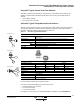
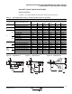
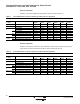
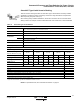
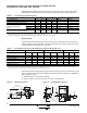
Table 20 lists the float travel distances for the screw-in float switches. Refer to Figure 13.
Figure 13: Travel Dimensions Table 20: Type H Float Travel Distances, in. (mm)
Float
Rod
Angle
RH
[1]
f1 f2 F
Minimum Maximum Minimum Maximum Minimum Maximum
45° — 6.22 (158) 2.25 (57) 4.50 (114) 2.00 (52) 4.50 (110) 4.25 (108) 9.00 (229)
90° offset 3.00 (76) 4.25 (108) 2.75 (70) 4.25 (108) 2.25 (57) 4.25 (108) 5.00 (127) 7.50 (191)
90° offset 4.25 (108) 5.50 (140) 3.50 (89) 5.50 (140) 2.75 (70) 4.00 (102) 6.25 (159) 9.50 (241)
90° offset 5.00 (127) 6.25 (159) 3.75 (95) 6.25 (159) 3.00 (76) 4.50 (110) 6.75 (171) 10.75 (273)
90° offset 7.00 (178) 8.25 (210) 4.75 (121) 8.25 (210) 3.75 (95) 5.75 (146) 8.50 (216) 14.00 (356)
1
Clearance from centerline of hub to side of tank.
F
f2
f1
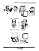
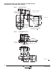
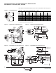
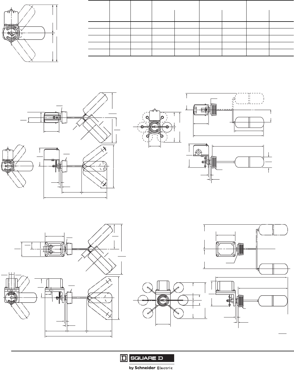
Figure 14: Type HG—45° Angle Dimensions Figure 15: Type HG—90° Offset Dimensions
Figure 16: Type HR/HW—45° Angle Dimensions Figure 17: Type HR/HW—90° Offset Dimensions
4.44
113
3.89
99
0.44
12
0.38
10
2.5
64
2.5
64
1.06
27
6.22
158
14.66
372
6.22
158
12.44
316
2.0
51
3.86
98
1.22
31
2.56
65
Pipe
Thread
Dia.
6.94
176
Extreme Float Position –
See Price Sheet
Across
Flats
Bushing
5.98
152
2.88
73
0.44
11
0.38
10
11.5
292
2.58
65
2.5" NPT
2.0
51
3.86
98
16.06
408
7.13
184
Across
Flats
Bushing
H
R
C
L
f2
f1
F
C
L
C
L
4.78
121
1.44
37
3.38
86
0.44
12
0.38
10
5.5
140
2.5
64
1.06
27
6.22
158
15.09
383
2.5
64
6.22
158
12.44
316
2.0
51
4.81
122
3.63
92
1.81
46
Pipe
Thread
Dia.
6.94
176
Extreme Float Position –
See Price Sheet
Across
Flats
Bushing
0.66
17
0.66
17
0.66
17
0.66
17
Two (2)
3/4-14 in.
entries for
1/2 in. conduit
6.22
158
0.44
11
0.38
10
3.63
92
11.5
292
7.13
184
2.5" NPT
2.58
65
2.0
51
16.94
430
Across Flats
Bushing
H
f2
f1
F
C
L
C
L
4.75
122
R
C
L
Dual Dimensions:
in.
mm