
Use and Care Manual

© 2011 Schneider Electric
All Rights Reserved
Commercial Pressure and Float Switches for Power Circuits
Float Switches—Class 9036, 9037, and 9038
62
03/2011
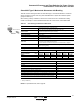
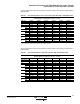
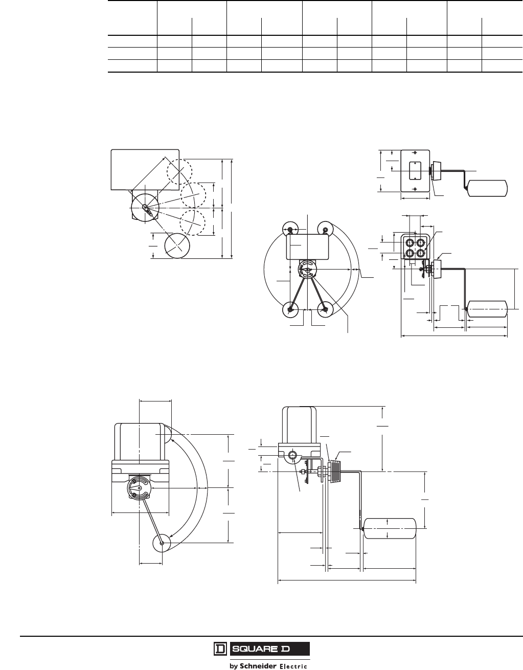
Table 25 lists the float travel distances for the screw-in float switches. Refer to Figure 20.
Table 25: Type C Float Travel Adjustments, in. (mm)
R
ABCD F
Min. Max. Min. Max. Min. Max. Min. Max. Min. Max.
4.25 (108)
[1]
1
CG33, CG34, CW33, CW34, CR33, CR34
2 (51) 3.5 (89) 3.5 (89) 4.75 (121) 2.5 (64) 3.75 (95) 3.5 (89) 4.75 (121) 7 (178) 9.5 (241)
5 (127)
[2]
2
CG35, CG36, CW35, CW36, CR35, CR36
2.25 (57) 3.75 (95) 4 (102) 5.25 (133) 2.75 (70) 3 (76) 4 (102) 5.25 (133) 8 (203) 10.5 (267)
7 (178)
[3]
3
CG31, CG32, CW31, CW32, CR31, CR32
2.5 (64) 5 (127) 5 (127) 7 (178) 2 (51) 4 (102) 5 (152) 7 (178) 10 (254) 14 (495)
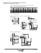
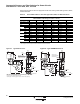
Figure 20: Travel Dimensions Figure 21: Type CG Dimensions
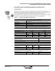
Figure 22: Type CR/CW Dimensions
R
A
C
B
D
F
2.5
64
1.97
50
5.94
151
2.59
66
0.88
22
0.38
10
0.44
11
0.44
11
4.0
102
7.0
179
17.81
452
1.75
44
2.5
64
6.5
165
max.
6.5
165
7.0
178
1.25
32
2.63
67
2.63
67
max.
To reverse the float, change the
operating link in the holes of the adjusting plate.
2.17
55
2.5
64
2.0
51
4.69
119
6.84
174
Pipe Tap
Bushing
Across
Flats
Combination knockouts,
0.5 in. (13 mm) and 0.75 in.
(19 mm) conduit, both ends
3.42
87
5.4
137
18.5
470
7.0
178
7.78
198
6.5
165
6.5
165
2.63
67
7.78
198
7.0
178
1.25
32
3.88
99
2.0
51
2.5
64
7.0
178
2.5
64
0.38
10
4.0
102
0.44
11
0.44
11
2.0
51
1.0
25
Pipe Tap
Bushing
Across
Flats
0.75-14
(19-356)
Pipe Tap,
Both Ends