
Instructions / Assembly


30 A General Duty Safety Switches 40269-522-03
Interruptores de seguridad de uso general de 30 A Rev. 01, 05/2011
© 2011 Schneider Electric All Rights Reserved / Reservados todos los derechos2
Installing the Switch Instalación del interruptor
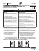
1. Mount the switch using the precut holes in the back
of the enclosure. See Figure 2.
1. Coloque el interruptor usando los agujeros precortados en la
parte posterior del gabinete. Vea la figura 2.
Figure / Figura 2: Mounting the Switch / Montaje del interruptor
2. Pull the conductors into the enclosure. 2. Jale los conductores hacia el interior del gabinete.
NOTE: To avoid damage to the conductor insulation,
use approved wire clamps, conduit, and bushings, or
other methods approved for this purpose.
NOTA: Para evitar daños al aislamiento de los conductores, utilice
abrazaderas para cables, tubo conduit y cojinetes aprobados o
cualquier otro método apropiado para este propósito.
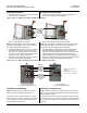
3. Following the wiring diagram on the cover, install the
main and neutral wires. If the equipment ground
wire (green wire or bare copper) is used, install the
wire in the service / equipment grounding bar (sold
separately) in the enclosure. See Figure 3.
3. Consulte el diagrama de alambrado en la cubierta al instalar los
conductores neutros y principales. Si se usa el conductor de
conexión a tierra del equipo (conductor verde o de cobre desnudo),
instale el conductor en la barra de puesta a tierra del equipo /
acometida (adquiridos por separado) en el gabinete. Vea la figura 3.
4. Torque all the wire binding screws per the instructions
provided on the enclosure wiring diagram.
4. Apriete los tornillos de sujeción de cables según las instrucciones
incluidas con el diagrama de alambrado del gabinete.
Figure / Figura 3: Wiring the Switch / Cómo conectar los cables del interruptor
Grounding and Bonding Conexión y puesta a tierra
NOTE: The switch must be grounded in accordance
with Article 250 of the National Electrical Code.
NOTA: El interruptor debe ser conectado a tierra de acuerdo con lo
especificado en el artículo 250 del Código nacional eléctrico (NEC)
de EUA y NOM-001-SEDE.
If the switch is used as service equipment, install the
neutral bonding screw (which connects the neutral bars
to the enclosure) in accordance with the directions on
the wiring diagram in the switch.
Si el interruptor se usa como equipo de acometida, instale el tornillo
de conexión al neutro (que conecta las barras de neutro al gabinete)
de acuerdo con las instrucciones en el diagrama de alambrado en el
interruptor.
Pre-cut holes
(4 total) /
Agujeros
precortados
(4 en total)
Cartridge Fuse Switch /
Interruptor tipo fusible de cartucho
Plug Fuse Switch /
Interruptor tipo fusible enchufable
Main wires /
Conductores
principales
Neutral wire /
Conductor de
neutro
Equipment
grounding wire /
Conductor de
puesta a tierra del
equipo
Cartridge Fuse Switch /
Interruptor tipo fusible de cartucho
Plug Fuse Switch /
Interruptor tipo fusible enchufable
NOTE: Grounding bar sold
separately.
NOTA: Adquiera la barra de
puesta a tierra por separado.