
Use and Care Guide

Preventive Maintenance and Troubleshooting Guidelines for Class 9013F and 9013G Pressure Switches 9013DB0701
Providing Routine Maintenance 12/2007
© 2007 Schneider Electric All Rights Reserved2
4. Check all plumbing connections. Verify that:
— The flange is not corroded.
— The fittings are secure and without white residue (lime deposits).
5. Check all electrical connections. Verify that:
— The wires are not pinched or frayed, and the insulation is not
cracked.
— There are no insects, contamination, or nests. If found, remove.
NOTE: Contacts may appear pitted. Do not sand or file the contacts. Do
not use chemicals to clean the contacts.
6. Check the system pressure using a pressure gauge.
7. Replace the cover.
8. Restore the power and confirm pump system operation.
9. Open a tap or spigot to confirm water flow.
10. For devices with low pressure cut-out (Form M4), hold the lever to Run
until the pressure is within 10 psi of the cut-in pressure.
Adjusting the Pressure Switch 1. Monitor the pressure gauge during operation to determine the points
where the pressure switch turns on and off.
2. Determine whether to adjust the cut-in, cut-out, or both.
3. If using a tank with an air bladder, determine what air pressure is
required in the bladder.
NOTE: Follow the manufacturer's instructions for setting air pressure to
the required level for the new adjusted pressure switch setting. When
instructions are not available, always set the air pressure in the bladder
to 2 psi below the new desired cut-in pressure. Perform the following
steps to set the air pressure:
a. Turn off the power to the pump.
b. Drain the water from the pressure tank.
c. Using a pressure gauge, take a pressure reading of the tank.
d. Using the air valve, add or remove air from the tank bladder until the
correct pressure is reached.
4. Perform Steps 1–6 of “Providing Routine Maintenance” on page 1.
5. To increase or decrease the cut-in and cut-out settings (while
maintaining the same differential) adjust the pressure switch with a
3/8 inch nut driver or socket as follows:
a. Turn the range nut clockwise for higher cut-in pressure, or counter-
clockwise for lower cut-in pressure. See Figure 1.
NOTE: Adjusting the cut-in setting does not change the differential.
As the cut-in value changes, the cut-out value changes by the same
amount and in the same direction. For example, increasing the cut-in
pressure by 10 psi will also result in an increase in the cut-out
pressure by 10 psi.
When lowering the pressure setting, remember that most bladder
tank water systems are designed for the bladder pressure to be 2 psi
below the cut-in point when there is no water in the tank.
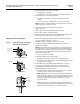
Figure 1: 9013F/9013G Pressure Switches
With Adjustable Differential
Range nut
Types FTG and FHG
Types FSG, FYG, and FRG
Type G
Range nut
Range nut
Differential
nut
Differential
nut