
Use and Care Manual


© 2011 Schneider Electric
All Rights Reserved
Commercial Pressure and Float Switches for Power Circuits
Electromechanical Pressure Switches, Class 9013 Types F and G
20
03/2011
TM
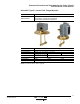
Types FRG, FHG, and G
Table 4: Environment
Type FRG FHG G
Conforming to Standards UL 508, NEC Article 430-84, ANSI/NSF Standard 61, FDA 21CFR.2600
Product approvals UL File E12158 CCN NKPZ , CSA File LR 25490 Class 321106
Degree of protection IP20, NEMA Type 1. NEMA Type 3R (only Types G•B) must be mounted in vertical position to maintain enclosure rating
Operating position IP20 and NEMA Type 1 in any position, NEMA Type 3R in the vertical position only
Operating rate 10 cycles/m
Repeat accuracy ±3% of the range
Ambient air temperature
Storage –22 to 158 °F (–30 to 70 °C)
Operation –22 to 257
°F (–30 to 125 °C)
Fluids Controlled Fresh water (or sea water with Form Q)
Materials
Cover: polypropylene, Noryl thermoplastic resin or equivalent for Type 3R,
Component material in contact with fluid: flange, zinc plated or equivalent (fluid entry), nitrile or equivalent rubber (diaphragm)
Fluid connection
1/8" NPSF internal, 1/4" NPSF internal, 1/2" NPT external, 1/4" bayonet (barbed), 90° elbow 1/4" bayonet, four-way flange, 3/8"
NPSF internal, 1/4" flare and other specials
Electrical connection 2 open side entries, 0.88 in. diameter, with two flats 3 knockouts for 1/2" conduit
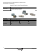
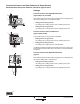
Table 5: Contact Block Characteristics
Type of contacts
One 2 pole, 2 N.C. (4 terminal) contacts, snap action
Type FRG: 1 or 2 pole, 2 N.O. (2 or 4 terminal) contacts, snap action
Resistance across terminals
< 25 mΩ
Short-circuit protection 5,000 A
Connection Screw clamp terminals. Clamping capacity up to 10 AWG (5.261 mm
2
)
Electrical durability 100,000 cycles
Mechanical durability 300,000 cycles (actual product life will vary based on electrical load, duty cycle, application, and environmental conditions)
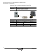
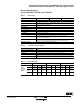
Table 6: Electrical Ratings
Type (1 pole)
[1]
1
Includes: FHG 2, 3, 4, 9, 12, 13, 14, 19, 42, 44, 49
FRG FHG G
Power
ratings of
controlled
motors
[2]
2
Type FRG and G devices include 1 N.O. and 1 N.C. contact (Form H).
Voltage
~ 1ØVac ~ 3ØVac Vdc ~ 1ØVac ~ 3ØVac Vdc ~ 1ØVac ~ 3ØVac Vdc
32 V —————————
115 V
0.75 kW
(1 hp)
—
0.18 kW
(.25 hp)
1.1 kW
(1.5 hp)
1.5 kW
(2 hp)
0.18 kW
(.25 hp)
0.75 kW
(1 hp)
—
0.37 kW
(.50 hp)
230 V
0.75 kW
(1 hp)
—
0.18 kW
(.25 hp)
1.5 kW
(2 hp)
2.2 kW
(3 hp)
0.18 kW
(.25 hp)
1.5 kW
(2 hp)
—
0.37 kW
(.50 hp)
460 / 575 V ————
0.75 kW
(1 hp)
—
1.5 kW
(2 hp)
—
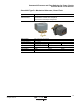
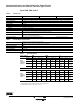
Type (2 pole)
[3]
3
Includes: FHG 22, 24, 29, 32, 33, 34, 39, 52, 54, 59
Power
ratings of
controlled
motors
Voltage
~ 1ØVac ~ 3ØVac Vdc ~ 1ØVac ~ 3ØVac Vdc ~ 1ØVac ~ 3ØVac Vdc
32 V ——
0.18 kW
(.25 hp)
——————
115 V
0.75 kW
(1 hp)
0.75 kW
(1 hp)
0.18 kW
(.25 hp)
1.5 kW
(2 hp)
2.2 kW
(3 hp)
0.37 kW
(.50 hp)
1.5 kW
(2 hp)
2.2 kW
(3 hp)
0.75 kW
(1 hp)
230 V
0.75 kW
(1 hp)
0.75 kW
(1 hp)
0.18 kW
(.25 hp)
2.2 kW
(3 hp)
3.7 kW
5 hp)
0.37 kW
(.50 hp)
2.2 kW
(3 hp)
3.7 kW
5hp)
0.75 kW
(1 hp)
460 / 575 V ————
0.75 kW
(1 hp)
—
3.7 kW
5hp)
3.7 kW
5hp)
—