63249-402-200/A2 1/2002 Instruction Bulletin Power Supply for use with POWERLINK™ G3 systems para utilizarse en los sistemas POWERLINK™ G3 (instructionnes en español: page 9) CONTENTS CONTENTS . . . . . . . . . . . . . . . . . . . . . . . . . . . . . . . . . . . . . . . . . . . . . . .1 INTRODUCTION . . . . . . . . . . . . . . . . . . . . . . . . . . . . . . . . . . . . . . . . . . .2 INSTALLING THE POWER SUPPLY . . . . . . . . . . . . . . . . . . . . . . . . . . . .3 CONNECTING TO A CONTROLLER . . . . .
Power Supply Introduction INTRODUCTION 63249-402-200/A2 1/2002 This bulletin explains how to install the POWERLINK G3 power supply, which is used to provide voltage for operating ECB-G3 remotely operated circuit breakers, POWERLINK G3 controllers, and POWERLINK G3 control busses. The power supply is installed in a NF panelboard by connecting the power supply, which mounts like a standard circuit breaker, to the interior bus. There are two different types of power supplies.
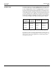
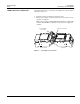
63249-402-200/A2 1/2002 INSTALLING THE POWER SUPPLY Power Supply Installing The Power Supply Follow these instructions to install the power supply on a NF panelboard. Figure 2 illustrates the installation. DANGER HAZARD OF ELECTRIC SHOCK, BURN, OR EXPLOSION • Turn off all power supplying the panelboard interior and the equipment in which it is installed before working on it. • Use a properly rated voltage sensing device to confirm that all power is off.
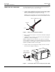
Power Supply Installing The Power Supply 63249-402-200/A2 1/2002 7. If you are installing power supply NF120PSG3L, NF240PSG3L, or NF277PSG3L, connect the red wire to the external power source and the white neutral wire to the panelboard neutral bar assembly. You must also connect the neutral side of the remote power source to the panelboard neutral bar assembly.
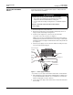
63249-402-200/A2 1/2002 CONNECTING TO A CONTROLLER Power Supply Connecting To A Control Module Follow these instructions to connect the power supply to the controller. Figure 3 illustrates the process. 1. Install the controller according to its instruction sheet. 2. Push the power supply connector plug into the power connection on the controller (see Figure 3).
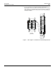
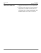
Power Supply Connecting To A Subnetwork CONNECTING TO A SUBNETWORK 63249-402-200/A2 1/2002 If your NF panelboard is part of a subnetwork, follow these instructions to connect the subnet connector to the power supply. 1. Using the 4-wire, 18 AWG subnet cable (General Cable 236100, Belden 27326, or equivalent) from the main network, insert one of the colored wires into the first terminal of the subnet connector plug.
63249-402-200/A2 1/2002 COMPLETING THE INSTALLATION © 2002 Schneider Electric All Rights Reserved Power Supply Completing The Installation 1. Verify that the power supply is installed correctly by noting whether the CL1 and CL2 LEDs are lit. If they are lit, the power supply was installed correctly. 2. To allow the power supply to protrude through the panelboard deadfront, remove the twist-outs in the deadfront corresponding with the power supply position. 3.
63249-402-200/A2 1/2002 Power Supply Completing The Installation Electrical equipment should be serviced only by qualified maintenance personnel. No responsibility is assumed by Square D for any consequences arising out of the use of this material. 8 Class No.
Manual de instrucciones 63249-402-200/A2 1/2002 Suministro de energía para utilizarse en los sistemas POWERLINK™ G3 for use with POWERLINK™ G3 systems (instructions in English: page 1) ÍNDICE ÍNDICE. . . . . . . . . . . . . . . . . . . . . . . . . . . . . . . . . . . . . . . . . . . . . . . . . . . . . 9 INTRODUCCIÓN . . . . . . . . . . . . . . . . . . . . . . . . . . . . . . . . . . . . . . . . . . . . 10 INSTALACIÓN DEL SUMINISTRO DE ENERGÍA . . . . . . . . . . . . . . . . . .
Suministro de energía Introducción INTRODUCCIÓN 63249-402-200/A2 1/2002 Este manual explica la manera en que deberá instalarse el suministro de energía POWERLINK G3, el cual se utiliza para proporcionar tensión a los interruptores automáticos ECB-G3 de funcionamiento remoto, controladores POWERLINK G3 y buses de control POWERLINK G3. El suministro de energía se instala en un tablero NF conectándolo al interior del bus. El montaje de este se realiza de la misma manera que un interruptor automático normal.
63249-402-200/A2 1/2002 INSTALACIÓN DEL SUMINISTRO DE ENERGÍA Suministro de energía Instalación del suministro de energía Siga estas instrucciones para instalar el suministro de energía en un tablero NF. La Figura 2 ilustra la instalación. PELIGRO RIESGO DE DESCARGA ELÉCTRICA, QUEMADURAS O EXPLOSIÓN • Antes de iniciar cualquier operación, apague el suministro eléctrico del interior del tablero y del equipo en el que está instalado.
Suministro de energía Instalación del suministro de energía 63249-402-200/A2 1/2002 6. Conecte el conductor neutro blanco del suministro de energía al conjunto de barra del neutro del tablero. 7. Si está instalando el suministro de energía NF120PSG3L, NF240PSG3L o NF277PSG3L, conecte el conductor rojo a la fuente de energía externa y el conductor neutro blanco al conjunto de barra del neutro del tablero.
63249-402-200/A2 1/2002 CONEXIÓN A UN CONTROLADOR Suministro de energía Conexión a un controlador Siga estas instrucciones para conectar el suministro de energía al controlador. La Figura 3 ilustra este proceso. 1. Instale el controlador de acuerdo con las instrucciones que lo acompañan. 2. Enchufe el conector del suministro de energía a la conexión de alimentación del controlador (vea la Figura 3).
Suministro de energía Conexión a una subred CONEXIÓN A UNA SUBRED 63249-402-200/A2 1/2002 Si su tablero NF es parte de una subred, siga estas instrucciones para conectar el conector de la subred al suministro de energía. 1. Utilizando el cable de subred de 4 hilos 0,82 mm2 (18 AWG) (cable general 236100, Belden 27326 o uno equivalente) de la red principal, inserte uno de los hilos de color en el primer terminal del enchufe del conector de la subred.
63249-402-200/A2 1/2002 TERMINACIÓN DE LA INSTALACIÓN © 2002 Schneider Electric Todos los derechos reservados Suministro de energía Terminación de la instalación 1. Compruebe que el suministro de energía esté correctamente instalado asegurándose de que estén iluminados los LED CL1 y CL2. Si están iluminados, el suministro de energía está correctamente instalado. 2.
63249-402-200/A2 1/2002 Importado en México por: Schneider Electric México, S.A. de C.V. Calz. Javier Rojo Gómez 1121-A Col. Gpe. del Moral 09300 México, D.F. Tel. 5804-5000 www.schneider-electric.com.mx 16 Clase no. 1210 Suministro de energía Terminación de la instalación Solamente el personal de mantenimiento eléctrico especializado deberá prestar servicios de mantenimiento al equipo eléctrico.
Addendum Anexo 80043-842-01 08/2018 Annexe California Proposition 65 Warning—Nickel Compounds and Bisphenol A (BPA) Advertencia de la Proposición 65 de California— compuestos de níquel y Bisfenol A (BPA) Avertissement concernant la Proposition 65 de Californie— composés de nickel et Bisphénol A (BPA) WARNING: This product can expose you to chemicals including Nickel compounds, which are known to the State of California to cause cancer, and Bisphenol A (BPA), which is known to the State of California to