
Brochure


8-26
© 2019 Schneider Electric
All Rights Reserved
UL 98 IEC Style Disconnect Switches LK4 Nonfusible and GS2 Fusible
Disconnect Switches
schneider-electric.us
Refer to Catalog 9421CT0301
8
OPERATING MECHANISMS AND
DISCONNECT SWITCHES
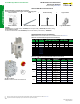
GS2 Fusible Disconnect Switches
GS2GU3N
GS2AH110 GS2AH130 GS2AH150
Auxiliary Contacts
GS1AD10 + GS2AM110
Shorting Links
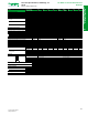
Table 8.65: GS Fusible IEC Style Disconnect Switches
Pole
Rating
(A)
Catalog No.
Maximum Horsepower Rating
Short Circuit Current
Rating, 600 Vac
Shaft
Style
240 V 480 V 600 V 250 Vdc Fuse SCCR kA
3 30 GS1DDU3 7.5 15 20 5 CC 100 AG
3 30 GS1DU3 7.5 15 20 5 J 100 AG
3 30 GS2EEU3 7.5 15 20 5 CC 100 B
3 30 GS2EU3N 7.5 15 20 5 J 100 B
3 60 GS2GU3N 15 30 50 10 J 100 B
3 100 GS2JU3N 30 60 75 20 J 200 B
3 200 GS2MU3N 60 125 150 40 J 200 B
3 400
GS2QU3N
125 250 350 50 J 200 B
3 600 GS2SU3 200 500 500 — J 200 C
3 800 GS2TU3 200 500 500 — J 200 C
Table 8.66: Handles and Shafts for GS Switches [6]
Rating
(A)
Handle
Shaft:
12.6 in.
(320 mm)
Shaft:
15.7 in.
(400 mm)
Shaft:
19.7 in.
(500 mm)
Shaft Guide
Shaft
Style
Support
Bracket
[7]
Catalog
No.
Type
Color
Catalog
No.
Catalog
No.
Catalog
No.
Catalog No.
30–60 GS2AH110
1, 3R,
12
Black
GS2AE8 GS2AE81 — GS2AEH12 AG —
30–60 GS2AH120
1, 3R,
12
Red/
Yellow
30–60 GS2AH410
4, 4X
Black
30–60 GS2AH420
4, 4X
Red/
Yellow
30–400 GS2AH130
1, 3R,
12
Black
GS2AE2 GS2AE21 GS2AE23 GS2AEH12 B GS2AESB
30–400 GS2AH140
1, 3R,
12
Red/
Yellow
30–400 GS2AH430
4, 4X
Black
30–400 GS2AH440
4, 4X
Red/
Yellow
600–
800
GS2AH150
1, 3R,
4, 4X,
12
Black
GS2AE5 GS2AE51 GS2AE53 GS2AEH12 C —
600–
800
GS2AH160
1, 3R,
4, 4X,
12
Red/
Yellow
NOTE: Hole adapter kit for GS1 to GS2 Handles: GS2AH100TO200.
Table 8.67: Auxiliary Contacts for GS Switches
[8]
Switch Amperes Catalog No. Description
30–800 GS1AM110
Auxiliary Contact, 1 N.O.
30–800 GS1AM101
Auxiliary Contact, 1 N.C.
30 GS1AD10
Auxiliary Contact Holder
Table 8.68: Shorting Links
For use on:
Shorting Links per Kit Catalog No.
GS2, 60 A
3 GS1AU203
GS2, 100 A
3 GS1AU303
GS2, 200 A
3 GS1AU403
GS2, 400 A
3 GS1AU503
GS2, 600–800 A
3 GS1AU803
Table 8.69: NFPA79 Kit
For Use With:
Description
Kit Part Number
GS2Q3N
NFPA 79 Internal Handle Kit 400 A Switch Shaft GS2AD040N
GS2GU3N, GS2GLU3N,
GS2JU3N, GS2JLU3N
NFPA 79 Internal Handle Kit 60–200 A Switch Shaft GS2AD030N
GS1DDU3, GS1DU3
NFPA 79 Internal Handle Kit for 5 mm Shafts GS1AD010
Table 8.70: Terminal Shrouds for GS Switches, Line or Load [9]
Switch Amperes Catalog No. Description
30–100 —
Standard on product
200 GS2AP43
GS2, 3-Pole, 200 A
400 GS2AP53
GS2, 3-Pole, 400 A
600–800 GS2AP73
GS2, 3-Pole, 600–800 A
[6] GS2AH100TO200–GS1 to GS2 Handle Adapter if using GS1 holes.
[7] Not for use with flange disconnects.
[8] GS1DU3 and GS1DDU3 switches allow up to 4 auxiliary contacts without adding contact holder GS1AD10. For more than 4 contacts, GS1AD10 is required.
[9] Order one terminal shroud per side. For example, order one terminal shroud for either the line side or load side; order two terminal shrouds for both the line side and load side.