Model SR554 Transformer Preamplifier
Model SR554 Transformer Preamplifier 1290-D Reamwood Avenue Sunnyvale, California 94089 Phone: (408) 744-9040 • Fax: (408) 744-9049 email: info@thinkSRS.com • www.thinkSRS.com Copyright © 1999 by SRS, Inc. All Rights Reserved. Revision 1.
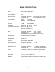
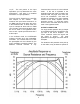
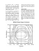
SR554 SPECIFICATIONS Inputs Single ended or differential Input Impedance 0.5 Ω Maximum Inputs Transformer and Buffer: Transformer only: Common Mode Range: Rejection: ± 100 VDC 140 dB @ 100 Hz Isolation > 40dB DC to 500 MHz Input Noise (Transformer and Buffer) 120 pV/√Hz @ 10 Hz (typical) 100 pV/√Hz @ 100 Hz 100 pV/√Hz @ 1000 Hz (see noise contours, pg. 5) Gain Transformer and Buffer: 500 (nominal) Transformer only: 100 (nominal) See Amplitude-Frequency Response Curve (pg 6).
2
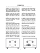
OPERATION indicator on the SR554 will light. The SR554 Transformer Preamplifier is designed to be used with all SRS Lock-in amplifiers. It can reduce input noise of a lock-in amplifier dramatically (as low as 100 pV/√Hz) and extends the lock-in’s full scale sensitivity (without expand). It also nearly eliminates noise radiated back from the lock-in amplifier to the users experiment. When used as a remote preamplifier, the SR554 can eliminate the effects of noise pickup on long signal cables.
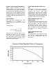
1.6 µF. The real portion of the input impedance (0.5 Ω) determines the noise performance. See page 7 for detailed information on input impedance. functional when the unit is in the buffered mode. If the unit is operated in the bypassed mode and power is applied, the overload LED may light even when the unit is not overloaded. This does not indicate an overload, but is due to leakage current of the buffer amplifier and its protection circuitry.
significant cable capacitance will create a low-pass filter with this output resistance as well, so short cables should always be used. the differential mode. In differential operation the (A) and (B) center conductors carry the signal and shielded preamp ground, and the shields are tied to the SR554 chassis. The (A) and (B) cables should be twisted together to prevent inductive pick-up. GAIN OF SR554 The actual gain of the SR554 is a function of the source impedance, frequency and the set gain.
EXTRA LOW NOISE MEASUREMENTS When making extremely low noise measurements, it is a good practice to connect the grounding plug of the SR554 to a ground point near the experiment. If a good ground is not available near the experiment, connect a wire from the lockin chassis (using a lug under one of the chassis screws) to the grounding lug of the SR554. USING THE SR554 WITH SRS LOCKINS The SR554 is not sensed through the 9 pin cable by SRS lock-in amplifiers.
ground point. If a ground is not available near the experiment, connect a wire to the lock-in using a lug under one of the chassis screws. USING THE SR554 WITHOUT AN SRS LOCK-IN The SR554 can be powered with an external power supply. Power is applied through the 9 pin connector as described below. PIN 1 6 7,8 VOLTAGE +20 V -20 V Ground INPUT IMPEDANCE The input impedance of the SR554 appears as a combination of 0.5 Ω and 0.5 H (in series) in parallel with 1.6 µF and several parasitic impedances.
8
PERFORMANCE TESTS Performance tests are designed to verify that the unit is performing within the specifications. 4) For each frequency, the following amplitude should be observed, ± 5%. Frequency 1.0 Hz 10 Hz 100 Hz 200 Hz 500 Hz 1 kHz 10 kHz 100 kHz Necessary Equipment: 1. Lock-In Amplifier Freq Range 0.1 Hz - 100 kHz Output Ampl 4 mV rms - 1 Vrms Output Z 50 Ω Recommended SRS SR850/830/810 2.
10
Part List Ref.
Part List Ref.