
User's Manual

12
to ON) sets the offset to the previously entered
value.
If an attempt is made to advance the offset value
beyond full scale, the ON LED will blink. An offset
up to 1.024 times the full scale sensitivity may be
entered. When the EXPAND is on, this is 10X the
full scale output.
Note that the offsets (either manual offset or those
generated by the REL function) represent a
fraction of the full scale reading, and so their
absolute value will change when the sensitivity
scale is changed. A signal which has been nulled
by an offset will not be nulled when the sensitivity
scale is changed. The analog meter and the
output BNC indicate the same value given by the
equation:
V
out
= 10A
e
(A
v
V
i
cosØ+V
os
) {if the output is X}
where...
A
e
= 1 or 10 per the Expand
A
v
= 1/Sensitivity
V
i
= magnitude of the signal
Ø = phase between signal & reference
V
os
= offset (fraction of FS < 1.024)
When the DISPLAY is X, X OFST, or X NOISE,
the OFFSET keys adjust the X OFFSET (which
affects the X (RCOSØ) output). When the
DISPLAY is R or R OFST, the OFFSET keys
adjust the R OFFSET. When the DISPLAY is X5,
the OFFSET up and down keys set the output
voltage of D/A output X5 (also on the rear panel)
up to ±10.24 V. Adjusting X5 will cancel the
RATIO output.
Expand Channel 1
The output EXPAND is toggled by pressing the
key in the Channel 1 EXPAND section. The
expand status is indicated by the X10, expand on,
and the X1, expand off, LED's. Only the Channel
1 OUTPUT is affected, the X (RCOSØ) output is
not expanded.
The X5 D/A output may not be expanded.
X (RCOSØ) Output
The analog output, X+X
ofst
, is available at the X
(RCOSØ) BNC connector. An input signal equal
in magnitude to the selected sensitivity which is in
phase with the reference oscillator will generate a
10V output. The output impedance is <1Ω and the
output current is limited to 20 mA.
The X (RCOSØ) output is affected by the X offset
but may not be expanded. The X (RCOSØ) is not
affected by the DISPLAY setting except for two
cases. When the DISPLAY is set to X OFST, the
X (RCOSØ) output is the X offset. When the
DISPLAY is set to X NOISE, the X (RCOSØ)
output has a bandwidth equal to the ENBW (1 or
10 Hz) instead of the time constant.
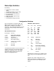
Channel 2 Display
The channel 2 outputs are summarized below. Y
is equal to RsinØ where Ø is the phase shift of the
signal relative to the reference oscillator of the
lock-in.
display CH2 Y
setting output
expand? offset? (RSINØ)
YY+Y
ofst
yes yes Y+Y
ofst
YOFST Y
ofst
yes yes Y
ofst
Ø Phase no no Y+Y
ofst
Ø Phase no no Y+Y
ofst
YNOISE Y noise yes yes Y+Y
ofst
(enbw)
X6 X6 no adjust Y+Y
ofst
The EXPAND and OFFSET conditions for each
display are retained when the DISPLAY is
changed. Thus, when the DISPLAY is changed
from Y to Ø, the EXPAND and OFFSET turn off. If
the DISPLAY is changed back to Y the EXPAND
and OFFSET return to conditions set for Y.
Ø Output
The phase, Ø, is given by the equation:
Ø = - tan
-1
{(Y+Y
ofst
)/(X+X
ofst
)}
Note that the X and Y offsets affect the value of Ø
while the X and Y expands do not.
The Phase Output voltage is 50 mV per degree
with a resolution of 2.5 mV or 1/20 of a degree.
The output range is from -180 to +180 degrees.
The phase output is updated every 3.5 mS. To
achieve maximum accuracy, the magnitude, R,
should be as large a fraction of full scale as