
User's Manual
39
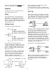
The CMRR is adjusted by the single turn
potentiometer located at A1 under the single
hole at the front of the signal shield. (The shield
is the aluminum box on the left side of the main
board). Using a small screwdriver, carefully
adjust the potentiometer to minimize the 100 Hz
output on the scope. Set the DISPLAY to R,Ø
and the sensitivity to 5µV and minimize the R
output on the Channel 1 meter.
Notch Filters
Set the reference frequency to 60.0 Hz (50.0
Hz). It is convenient to use the SYNC output of
the signal generator as the reference input if it is
available. Connect the sine output of the signal
generator to the A input and set the input
selector to A. With the SENSITIVITY at 100mV,
adjust the amplitude of the input signal to 100
mV (full scale).
Set the LINE NOTCH to IN, the SENSITIVITY to
10mV, and the DYN RES to LOW. Connect the
scope to the SIGNAL MONITOR output on the
rear panel. Set the scope to AC coupled,
0.2V/div, 10mS/div. Trigger the scope externally
using the reference input signal.
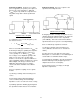
The LINE NOTCH frequency and depth are
adjusted by the pair of 20 turn potentiometers
located under the middle two holes in the signal
shield (row 4 on the circuit board). Using a
small screwdriver, carefully adjust one pot until
the line output on the scope is minimized. Then
adjust the other pot until the output is minimized.
Iterate between the two pots until there is no
further improvement. Set the SENSITIVITY to
5mV, 2mV, and 1mV, repeating the adjustments
at each sensitivity.
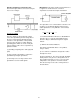
Repeat this procedure using a reference
frequency of 120.0 Hz (100.0 Hz) and the
LINEX2 NOTCH filter. The LINEX2 NOTCH is
adjusted by the pair of 20 turn potentiometers
located under the back two holes in the signal
shield (row 5 on the circuit board).
Replace the top panel.
Replacing the Front-End Transistors
Both the voltage and current front end transistors
(Q101 and Q102) are 2N6485 (IMF6485) dual
JFETS. These transistors are selected at the factory
to meet the noise specifications.
This section outlines their replacement procedure in
the event that they become damaged during use.
1) Remove the AC power cord from the unit.
2) Remove top and bottom panels.
3) Release the signal shields by removing the four
screws which hold it onto the circuit board. Be
careful not to lose the nuts. Carefully slide the
shields back and then lift them out.
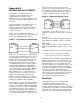
4) The input transistors are located on the main
board, just behind the input selector switch.
Q101 is the voltage (A, A-B) front end, and
Q102 is the current (I) front end. Desolder and
replace the appropriate transistor.
5) Replace the signal shields. Be careful to check
that the shields do not touch any circuit board
traces around their edges.
6) Replace the top and bottom panels.
7) If Q101, the voltage front end has just been
replaced, the Common Mode Rejection needs to
be readjusted using the procedure described in
the Amplifier Adjustments section.