
User's Manual


5
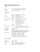
Front Panel Summary
Signal Inputs Single Ended (A), True Differential (A-B), or Current (I)
Signal Filters Bandpass: Q-of-5 Auto-tracking filter (In or Out)
Line Notch: Q-of-10 Notch Filter at line frequency (In or Out)
2XLine Notch: Q-of-10 Notch Filter at twice line frequency (In or Out)
Sensitivity Full scale sensitivity from 100 nV to 500 mV RMS for voltage inputs
or from 100 fA to 500 nA RMS for current inputs.
Dynamic Reserve Select Dynamic Reserve
Stability Sensitivity Ranges
LOW 20 dB 5 ppm 1 µV to 500 mV
NORM 40 dB 50 ppm 100 nV to 50 mV
HIGH 60 dB 500 ppm 100 nV to 5 mV
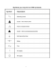
Status Indicators OVLD Signal Overload
UNLK PLL is not locked to the reference input
ERR Illegal or Unrecognized command
ACT RS232 or GPIB interface Activity
REM Remote mode: front panel has been locked-out
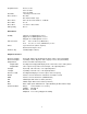
Display Select Channel 1 Channel 2
X (RcosØ) Y (RsinØ)
X Offset Y Offset
R (Magnitude) Ø (Phase)
R Offset Ø (no offset)
X Noise Y Noise
X5 (D/A) X6 (D/A)
Analog Meters Displays Channel 1 and 2 Outputs as a fraction of full scale
Output LCD's Displays the Channel 1 and 2 Outputs in absolute units
Output BNC's Channel 1 and 2 Outputs follow Analog Meters, ± 10 V for ± full scale
Expand Multiplies the Channel 1 or 2 Analog Meter and Output voltage by a factor X1 or X10.
REL Set the Channel 1 or 2 Offset to null the output: subsequent readings are relative
readings. REL with phase display performs auto-phasing. REL with X5, X6 display
zeroes the D/A outputs.
Offset Enables or Disables Offset, and allows any offset (up to full scale) to be entered. X, Y,
and R may be offset and X5, X6 may be adjusted. Phase is offset using the reference
phase shift.
X BNC X (RcosØ) output, ± 10V full scale
Y BNC Y (RsinØ) output, ± 10V full scale
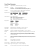
Reference Input 1 MΩ Input, 0.5 Hz to 100 KHz, 100 mV minimum
Reference Trigger Trigger on rising edge, zero crossing, or falling edge
f/2f Mode PLL can lock to either X1 or X2 of the reference input frequency