MODEL SR550/552 Voltage Pre-amplifier 1290-D Reamwood Avenue Sunnyvale, CA 94089 U.S.A. Phone: (408) 744-9040, Fax: (408) 744-9049 Email: info@thinkSRS.com • www.thinkSRS.com Copyright © 1999, 2001 Stanford Research Systems, Inc. All Rights Reserved Rev. 2.
Voltage Pre-amplifier manual Stanford Research Systems
SR550 Preamplifier Specifications Summary Ω ! " # ! $ ! % &'( !)√*+ *+ ,' !)√*+ *+ & !)√*+ *+ -. / " 0 " 2 0 5 $ $ $ " ) & 5 6 . 5 . ! 1 3 4 *+ 9 : 7 18 6 . . " " & 7 18 # . .
OPERATING INSTRUCTIONS - " ! : 86 " ) & 18 9 : 18 ' - " # .
DYN RES FS Sensitivity SR550 Gain 7=A E ! ! ! F ! E ! ! ! F ! * 5* ( E µ! µ! µ! F µ! %=" , A " $ # . ! ' - $ $ ! # 18 ' " # . !$ # .
THE SR550 WITHOUT A LOCK-IN - " .
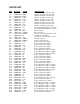
PARTS LIST REF.
" && A G G G & G , G G ( G > L L L L L L L L L L ,8 8 &8 &8 &8 &8 &8 &8 &8 8 8 8 8 8 8 8 8 8 8 8, 8 > ,8& H8& 3&8&, (8&, >(8&, (8&, &H8&, 8 ,&8 >38 & 8 & , 8 3 ,38 HH8 &8 , 8 > >&8 Z0 Z0 7-00097-720 7-00098-720 > J 9:9>37 >H7 7 &&3 7> 95 7> >,*/ &3 &)H? ,8, JB: ,8, @&) ( ) 8 ),? M , *BB,8, @ ),: " ==4%/ 9438943) % 7 SR550-2 SR550-3 Resistor, Carbon Film, 1/4W, 5% Switch, On-None-On, Toggle, Right Angle Transistor, TO-92 Package Transistor, TO-92
MODEL SR552 Voltage Pre-amplifier manual Stanford Research Systems
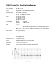
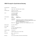
SR552 Preamplifier Specifications Summary IInput Impedance 100 KΩ + 25 pF Inputs Single ended or differential (switch selectable) Maximum Inputs 70 mV rms for overload Damage threshold: 20 Vac, 50 Vdc Noise 1.4 nV/√Hz at 1000 Hz 1.6 nV/√Hz at 100 Hz 2.5 nV/√Hz at 10 Hz (all figures are Typical) Common Mode Range: Rejection: Gain 10,20,50,100 SR510/530 DSP Lock-Ins 1 Volt peak 100 dB at 100 Hz Automatically set by SR510 or SR530 Lock-In depending on sensitivity and dynamic reserve.
Noise Figure Contour
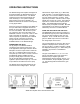
OPERATING INSTRUCTIONS The SR552 Voltage Pre-Amplifier is designed to be used with either the SR510/530 lock-ins as well as the newer DSP lock-ins. The SR552 reduces the input noise and extends the full scale sensitivity to 10 nV (without expand). When used as a remote pre-amplifier, the SR552 can eliminate the effects of noise pickup on long signal cables. Power and control are supplied to the SR552 via the 9 pin cable which is supplied with the unit.
DYN RES FS Sensitivity SR552 Gain LOW 20 db > 50 mV 50 mV 20 mV < 20 mV 10 20 50 100 USING THE SR552 WITH SRS DSP LOCK-INS The SR552 is not sensed by the DSP lock-ins. The DSP lock-in does NOT compensate for the gain of the preamp. The gain of the preamp is set to 10. Measurements made with the preamp need to be divided by 100. NORM 40 db > 5 mV 5 mV 2 mV < 2 mV 10 20 50 100 The SR552 is AC coupled from 1 Hz to 100 kHz. Set the lock-in input to AC coupled since the signal must be above 1 Hz.
dual phase lock-in, use the R output to avoid phase shifts. The SR552 without a lock-in The SR552 can be powered with an external power supply. Power is applied through the 9 pin connector as described below. Pin 1 2 6 7,8 Voltage +20 V +5 V -20 V Ground Current 100 mA 10 mA 100 mA All three voltages are required. Pins 7 and 8 should be tied together. All other pins should be left open. The gain will be 100 in this configuration.
PARTS LIST REF.
R 33 RU7A RU7B SW1 U1 U2 U3 U4 U5 U7 Z0 Z0 Z0 Z0 Z0 Z0 Z0 Z0 Z0 Z0 Z0 4-00082-401 4-00032-401 4-00032-401 2-00025-217 3-00124-325 3-00118-325 3-00193-340 8-00085-860 3-00076-340 3-00038-340 0-00025-005 0-00043-011 0-00079-031 0-00122-053 0-00140-009 0-00149-020 0-00188-000 1-00003-120 1-00041-170 1-00073-120 7-00098-720 Z0 7-00128-720 470K 100K 100K SPDT 79L15 78L15 LM339 SR513 ASSY DG211 74HC139 3/8" 4-40 KEP 4-40X3/16 M/F 2-1/4" #24 SHEET 4-40X1/4PF SR552FOOT BNC DB9-DB9/MM INSL SR552-3 SR552-2 Resis