SRS Robot Level 1 Kit Table of Contents Getting Started ................................................................................................................... 2 Computer Requirements..................................................................................................... 2 Recommended Equipment ................................................................................................. 2 Kit Contents .............................................................................
Getting Started Getting Started Congratulations on your purchase of a Seattle Robotics Society Level 1 Robot Kit! Here are suggested steps for getting your robot assembled and running. Read through the “Computer Requirements” and “Recommended Equipment” sections to be sure you have the materials you need. Compare your kit’s parts with the lists in the “Kit Contents” section to verify that you can correctly identify each of the parts in the kit.
Kit Contents Kit Contents Level 1 Kit Anti-Static Bag Item Fairchild QRB1134 light sensor ARC 1.1 PCB ATMEGA16-16PC microcontroller TI 754410 H-bridge RS232 driver LM2940CT-5.0 voltage regulator ZTT-16.0MX ceramic resonator red LED green LED 47 uf 16v electrolytic capacitor .1 uf ceramic Z7T .1" capacitor diode, 1A 180 ohm 1/8 W resistor (brown-gray-brown) 330 ohm 1/8 W resistor (orange-orange-brown) 680 ohm 1/8 W resistor (blue-gray-brown) 1k ohm 1/8 W resistor (brown-black-red) 4.
Kit Contents 2-56 x 1" machine screw small wood screw (in motor if not here) 4-40 nut 2-56 nut #4 flat washer #4 lock washer #2 lock washer 4 2 5 4 8 2 8 Loose Item chassis Solarbotics GM8 motor wheel rubber band (for wheel) Tamiya ball caster (pair) battery holder velcro, 1/2" x 16" strap 4-conductor cable, 3' 10-conductor ribbon cable, 3' servo cable insulated copper wire, 7" Qty 1 2 2 4 1 1 1 1 1 2 2 McMaster-Carr 91772A086 McMaster-Carr McMaster-Carr McMaster-Carr McMaster-Carr McMaster-Carr 9048
AVR Robot Controller 1.1 Assembly Instructions AVR Robot Controller 1.1 Assembly Instructions Preparation Identify the parts used in the AVR Robot Controller (ARC). Refer to the Kit Contents section for a list of parts in each bag. • Anti-Static Bag: everything except the QRB1134 light sensors. • Electro-Mechanical Bag: everything except the velcro, mounting squares, shrink tubing, and rubber bands. • Loose items: the battery holder, 4-conductor cable, and ribbon cable.
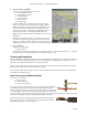
AVR Robot Controller 1.1 Assembly Instructions Prepare Boards The PCB comes with a serial adapter and a programming adapter that need to be detached. First break the long line of holes. You might find it easier to break if you run a razor knife along the top and bottom of the line of holes. Then snap the two smaller boards apart. Finally, if you want, you can sand or file the rough edges smooth.
AVR Robot Controller 1.1 Assembly Instructions Small capacitors and LEDs The picture on the right shows the locations for: 8 - 0.1uF capacitors 1 - red LED 1 - green LED Orientation of the small capacitors is not important. Note that one of the capacitors (second from the top) will be under the microcontroller. Be sure that it sticks up no higher than the DIP socket (to be installed in the next step). You may need to bend the capacitor’s leads a bit to get it to sit close enough to the board.
AVR Robot Controller 1.1 Assembly Instructions Sockets, headers, and jumper The picture on the right shows the locations for: 2 - 1x3 boardmount sockets 3 - 1x4 boardmount sockets 3 - 1x3 male headers 2 - 2x3 male headers 1 - 2x5 male header 1 - shorting jumper Install the sockets along on the front of the board (as shown at the top of the picture). The headers should be installed with the shorter end of the pins inserted into the board.
AVR Robot Controller 1.1 Assembly Instructions Install Chips Be sure to inspect the board before applying power. Connect the battery pack to the 3-pin header next to the switch (JP13). With the switch in the on position (toward the near edge of the board) the red power LED should light. Now you can install the various chips. (Turn off power to the board first.
AVR Robot Controller 1.1 Software Tools Programming Cable The kit is supplied with material to make a programming cable that works with the BASCOM Basic Compiler or the AVRDUDE program (included in the WinAVR suite for C/C++ programming). BASCOM and AVRDUDE work with any third party programmer that has an Atmel 10-pin programming socket, so you only need to build the cable if you don’t already own a programmer. The programmer uses a male DB25 connector that plugs directly into a PC printer (parallel) port.
AVR Robot Controller 1.1 Software Tools Tool Options Free, high-quality tools are available for the Atmel AVR series of microcontrollers. On Windows systems, two popular options are the BASCOM (BASIC) compiler and the WinAVR suite of tools for C/C++ programming. Mac OS X supports the avr-gcc C/C++ compiler (which should work equally well on Linux and FreeBSD). The following sections each provide instructions for installing a compiler and downloading a simple program to your ARC board.
AVR Robot Controller 1.1 Software Tools Double-click on “LaunchPN.bat” in the “C Samples” folder. This will launch Programmers Notepad with the path changes needed by the compiler and downloader. (If you installed WinAVR in a non-default location, you’ll need to edit this batch file.) While power to the ARC board is off, plug the programming cable into the ISP header on the board and the parallel (printer) port of a PC.
AVR Robot Controller 1.1 Software Tools to 8 MHz; (2) enable brown-out detection; (3) disable JTAG; and (4) disable erasing EEPROM when downloading a new program. Please refer to the chip data sheet (www.atmel.com) for a complete list of the fuse bits. The following steps set the microcontroller to the suggested state. If you are using BASCOM-AVR: Connect the programmer to your board as above, select “Send to Chip” from the Program menu to bring up the Sample programmer window.
Chassis Assembly Chassis Assembly Preparation Identify the parts used in the chassis. Refer to the Kit Contents section for a list of parts in each bag. • Anti-Static Bag: QRB1134 light sensors. • Electro-Mechanical Bag: velcro, mounting squares, shrink tubing, and rubber bands. • Hardware Bag: everything except the four 1” standoffs and eight of the 4-40 x 1/4” machine screws. • Loose items: everything except the 4-conductor cable and ribbon cable. Remove the paper from the (twelve) chassis pieces.
Chassis Assembly Light Sensors Find the two copies of the “light sensor plate” pictured on the right. Hardware: 1 4-40 x 1” screw 1 4-40 nut 2 4-40 lock washers 4 4-40 flat washers Stack items onto the screw as follows: lock washer, plate, 2 flat washers, both light sensors (orient them the same way), 2 flat washers, the other plate (oriented the same direction as the first plate), lock washer, nut. Tighten. Bottom Plate The picture below shows the bottom plate.
Chassis Assembly Strip about 2” from one end of each 7” length of 18 AWG insulated wire. Hardware (for one side): 1 4-40 x 1/4” round standoff 1 4-40 x 1/4” screw 2 4-40 x 1/2” screws 2 4-40 washers 2 4-40 nuts Mount the standoff in hole C, on the same side of the plate as the caster, using the 1/4” screw. C B A For holes A and B, put a washer on a 1/2” screw and put the screw through the plate from the side with the caster. Attach a nut (on the side with the standoffs).
Chassis Assembly Flip the top plate over. The screws will be visible, and the standoffs will be underneath (and you should have a hole in the lower right corner). Find this piece (the battery spacer), and hold it like this: You will mount this to what is the underside of the top plate (which is now face up since you flipped it over!) Stick the two mounting squares onto the battery spacer. Then, flip the spacer over and attach it to the top plate, as shown on the far right.
Wiring Connections Leftover Parts At this point, your robot is together and you’re probably wondering about those extra parts. They are used for Levels 2 and 3 of the SRS Robot. Here’s a summary. The hardware bag should still contain four 1” standoffs and eight 1/4” machine screws. They are explained below. There will be five plastic chassis pieces remaining: These two pieces are used to hold Sharp GP2D12 infrared distance sensors (part of the Level 2 kit).
ATmega16 Programming ATmega16 Programming Part 1 11-3-2005 19
ATmega16 Programming 20 11-3-2005
ATmega16 Programming Part 2 11-3-2005 21
ATmega16 Programming 22 11-3-2005
ATmega16 Programming Part 3 11-3-2005 23
ATmega16 Programming 24 11-3-2005
ATmega16 Programming 11-3-2005 25
ATmega16 Programming Part 4 26 11-3-2005
Sample Programs Sample Programs There are sample programs available from http://www.seattlerobotics.org/WorkshopRobot/Level1/ (or the Workshop CD’s “Samples” folder). There are versions for BASCOM (BASIC) and C. The program files contain descriptive comments to explain what the code is doing. The programming concepts are explained in the slides in the “ATmega16 Programming” section. The “Program Descriptions” section below describes the programs that are listed at the end of each section of slides.
Sample Programs A good way to get started with a new program is to make a copy of a folder for an existing program, then rename the new folder and its .bas or .c file. (For C programs, you will also need to edit the makefile to reflect the name change for the .c file. Look for the SRC= line. You may also change the PRG= line for consistency.) C Programming Each sample program is in its own folder.
Sample Programs Challenges: o Make a bumper touch cause the robot to back up, turn away from the obstacle, and then resume exploring. (The BumpNGo program shows one possible solution, including waiting for a bump at the beginning of the program before starting.) o Teach the robot how to navigate a (specific) obstacle course. o “Bounce” along a wall: drive until you touch a wall, then turn away from it and arc back toward it, continuing to “bounce” along.
Sample Programs Program 8 Purpose: Learn to use the Timer/Counter for timing. This program flashes a LED at a specific rate while reading sensors. Program: Timer Extensions: o Change the flash rate. o Add more code to the loop, e.g. showing sensor values. Notice that the flashing still maintains its rate, with no changes necessary. Challenges: o Modify your EEPROM program to use the timer instead of WaitMs when showing sensor readings. o Read sensors for 10 milliseconds and calculate the average value.
AVR Robot Controller 1.1 Hardware Description AVR Robot Controller 1.1 Hardware Description The Level 1 Robot Kit ships with an ATmega16 microcontroller. The Atmel AVR microcontrollers are designed to be pin- and code-compatible where possible. In this case, for example, you could substitute an ATmega8535 or ATmega32. These chips will all function in the ARC board with minimal software changes (typically just a recompile), the primary difference being the amount of internal memory available.
AVR Robot Controller 1.1 Hardware Description Expansion Headers JP3 and JP10 Refer to the schematic for the connections to these headers. All CPU I/O, +5v, ground, +/- 10v and battery voltages are supplied. JP3 supplies +5v and ground from the analog section. JP10 supplies +5v, ground, +10v and –10v from the digital section. The +/-10v is from the serial interface chip and can only supply about 10ma of current. This is sufficient for one or two low powered op-amps.
AVR Robot Controller 1.1 Hardware Description R/C servo output When driving an R/C servo, use the pins nearest to the edge of the board. They are marked with letters indicating polarity: “W R B” for White, Red, and Black. Some servo brands substitute yellow for white. When driving servos, the board has the option of selecting regulated +5v or raw battery voltage to drive the servos. R/C servos are usually rated at 4.8v and 6.0v, but can be driven with 9-12 volts without damaging the internal electronics.
AVR Robot Controller 1.1 Schematic AVR Robot Controller 1.