
- SRS Robot Level 1 Kit


AVR Robot Controller 1.1 Hardware Description
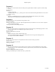
R/C servo output
When driving an R/C servo, use the pins nearest to the edge of the board. They
are marked with letters indicating polarity: “W R B” for White, Red, and Black.
Some servo brands substitute yellow for white.
When driving servos, the board has the option of selecting regulated +5v or raw
battery voltage to drive the servos. R/C servos are usually rated at 4.8v and 6.0v,
but can be driven with 9-12 volts without damaging the internal electronics.
Higher voltages will increase speed and torque of the motors. A rough rule of
thumb is that doubling the voltage (9.6 vs. 4.8) doubles the RPM and the maximum torque of the servo.
Power Source
A 3-pin header is used to select the power source for the Motor Headers (V+ in
the picture above) when used for R/C servos or encoders. There are two options:
regulated +5 volts, or the battery supply. Use the shorting jumper to make this
connection. The H-Bridge is always connected to the main power source.
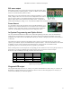
In-System Programming and Option Select
The 2x5 pin header labeled ISP (and JP9) is for In-System Programming of the CPU. This is the mechanism by
which the CPU is loaded with a new program. This connector works with any Kanda-compatible 10-pin AVR
programmer. The cable connects to the ISP header with the pin 1 marker (a triangle) next to the 1 and caret printed
on the board.
The header has a dual use. When the programming cable is removed, several of the pins may be used to select
options or give feedback. All pins are available from the expansion headers – refer to the schematic for more details.
In addition, one pin is used to control the program LED (green). This gives both visual feedback while
programming, and can be controlled by the user’s program to give feedback.
When a shorting bar is across the inputs, the corresponding pin value will be zero. There are no pull-up resistors on
these inputs, so you need to enable the CPU pull-up on those ports if you intend to use them as inputs.
Reset has no CPU readable input. It simply resets the CPU when shorted.
Pin Pair label Direction IO port
9 A Input Pinb.6 (MISO)
7 B Input Pinb.7 (SCK)
5 Input CPU reset
3 C (Prog LED) Input/Output Pinb.4/Portb.4
1 Output Portb.5 (MOSI)
Options I/O port assignments
Program LED output
The program LED output is inverted. I.e. writing a 0 to portb.4 will illuminate the LED, writing a 1 will turn it off.
Remember to configure that I/O pin as an output or it will never turn on. When using Option C as an input, you
cannot use the LED (they are connected together).
11-3-2005 33