
User's Manual


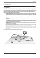
Table Of Contents
- 1 Glossary 5
- 2 Notices 6
- 3 Introduction 9
- 4 AIS AtoN product variants 13
- 5 Installation 14
- 6 Transceiver and Sensor Interface connections 19
- 7 Connecting external sensors and systems 23
- 8 Configuration using proAtoN 31
- 9 Operation 50
- 10 Data messages and data sources 51
- 11 Manual configuration 59
- 12 Technical specification 68
- 13 Firmware upgrade procedure 73
- 1 Glossary
- 2 Notices
- 3 Introduction
- 4 AIS AtoN product variants
- 5 Installation
- Figure 3 Typical AIS AtoN transceiver system connections
- Figure 4 Typical AIS AtoN transceiver and Sensor Interface system connections
- 1. Mount the Transceiver in a suitable location on the physical Aid to Navigation.
- 2. Install a VHF antenna according to the manufacturers instructions.
- 3. Install the supplied GNSS antenna.
- 4. Connect any sensor interfaces and light / RACON monitoring signals.
- 5. Connect power to the AIS AtoN transceiver and optional Sensor Interface.
- 6. Configure and commission the AIS AtoN transceiver and optional Sensor Interface via USB (note that this step can be carried out on shore prior to installation in a remote location).
- 5.1 What’s in the box (AIS AtoN transceiver)
- 5.2 What’s in the box (Sensor Interface)
- 5.3 Preparing for installation
- 5.3.1 Tools and wiring accessories
- 5.3.2 VHF antenna and cable
- 5.3.3 PC for configuration
- 5.4 Mounting the AIS AtoN transceiver and Sensor Interface
- 6 Transceiver and Sensor Interface connections
- 6.1 AIS AtoN transceiver connections
- 6.1.1 Power and USB connector
- 6.1.2 18 way Link connector
- 6.1.3 Using the 18 way link connector for direct connection of external equipment
- 6.1.4 VHF antenna connector
- 6.1.5 GNSS antenna connector
- 6.1.6 Earth connection stud
- 6.2 Sensor Interface connections
- 6.2.1 USB connector
- 6.2.2 Sensor 1 connector
- 6.2.3 Sensor 2 connector
- 6.2.4 Link connector
- 7 Connecting external sensors and systems
- 7.1 Connecting sensors and systems to the AIS AtoN Transceiver
- 7.1.1 Light ON/OFF interface
- 7.1.2 Light health interface
- 7.1.3 RACON status interface
- 7.1.4 AtoN Status source and configuration
- 7.1.5 NMEA0183 port
- 7.2 Connecting sensors and systems to the Sensor Interface
- 7.2.1 Isolated analogue inputs
- 7.2.2 Non-isolated analogue inputs
- 7.2.3 Light current sense loop
- 7.2.4 Isolated digital inputs
- 7.2.5 Non-isolated digital inputs/outputs
- 7.2.6 Isolated RS422 / NMEA0183 port
- 7.2.7 RS232 ports
- 7.2.8 SDI-12 interface
- 7.2.9 Relay drive output
- 7.2.10 Input voltage monitor
- 8 Configuration using proAtoN
- 8.1 proAtoN installation
- 8.2 Application layout
- 8.2.1 COM Port selection
- 8.2.2 Read / Write configuration
- 8.2.3 Transceiver configuration mode tabs
- 8.2.4 Sensor configuration mode tabs
- 8.2.5 Synchronisation status
- 8.2.6 Status bar
- 8.3 AIS AtoN transceiver configuration
- 8.3.1 Configuration of ‘Real’ AtoN parameters
- 8.3.2 Message schedule configuration
- Default messages
- Adding additional messages to the schedule
- Access scheme selection
- 8.3.3 FATDMA Schedule configuration
- Channel 1 start UTC
- Channel 1 start slot
- Channel 1 interval
- Channel 2 start UTC
- Channel 2 start slot
- Channel 2 interval
- Example FATDMA schedule
- 8.3.4 RATDMA Schedule configuration
- Channel 1 start UTC
- Channel 1 interval
- Channel 2 start UTC
- Channel 2 interval
- Example RATDMA schedule
- 8.3.5 Virtual AtoN configuration
- Virtual / Synthetic AtoN
- Virtual / Synthetic AtoN Details
- Virtual AtoN schedule
- 8.3.6 Status input configuration tab
- Current status (message 21)
- Light & RACON configuration
- Status bit source
- Status bit logic
- 8.3.7 Alert messages
- BIIT failure actions
- Vessel proximity alert
- Off position alert
- SART Relay Mode
- 8.4 Transceiver diagnostics
- 8.4.1 GNSS tab
- 8.4.2 Serial data tab
- 8.4.3 Diagnostics tab
- AtoN Details
- Power status
- Report generation
- Reported messages
- Active alarms
- 8.5 Sensor configuration
- 8.5.1 Sensor settings
- 8.5.2 ADC settings tab
- Light Current Sense group
- Current Sense ADC Scaling
- Voltage Measurement Scaling
- 8.5.3 Message settings tab
- Message #6 Configuration
- Message #8 Configuration
- 8.5.4 System information
- System Information
- Digital Input Status
- Sensor Health
- 8.5.5 Live data tab
- ADC Data
- 8.6 Other features
- 8.6.1 Offline configuration (applies to transceiver configuration mode only)
- 9 Operation
- 10 Data messages and data sources
- 10.1 Configurations without the Sensor Interface
- 10.2 Configurations with the Sensor Interface
- 10.2.1 AIS AtoN transceiver configuration
- 10.2.2 Configuration of the Sensor Interface
- 10.2.3 Accessing the Sensor Interface shell
- 10.2.4 General Sensor Interface configuration commands
- 10.2.5 Zeni Lite Message #6 configuration commands
- 10.2.6 ADC configuration commands
- 10.2.7 ADC Scaling
- 10.2.8 Message #6 Data Mapping
- 10.2.9 External device support
- 11 Manual configuration
- 11.1 Basic Type 1 AIS AtoN configuration (FATDMA operation)
- 11.2 NMEA0183 / IEC61162 configuration sentences
- 11.2.1 AAR - Configure broadcast rates for AtoN station
- 11.2.2 ACE - Extended general AtoN Station configuration
- 11.2.3 ACF - General AtoN Station configuration
- 11.2.4 AFB - Forced broadcast
- 11.2.5 AFC - AtoN function ID capability
- 11.2.6 AID - MMSI configuration
- 11.2.7 ARW -Configure the receiver turn-on times
- 11.2.8 MCR - Configure proprietary AtoN control
- 11.2.9 MPR - Message configuration of payload re-broadcast
- 11.2.10 TSP - Transmit slot prohibit
- 11.2.11 VER - Version
- 11.3 Proprietary configuration sentences
- 11.3.1 Status Bit Source
- 11.3.2 Status Bit Source Query
- 11.3.3 Light / RACON configuration
- 11.3.4 Light / RACON configuration query
- 11.3.5 General MCR query
- 12 Technical specification
- 12.1 Applicable equipment standards
- 12.2 AIS AtoN transceiver specification
- 12.2.1 Physical
- 12.2.2 Environmental
- 12.2.3 Electrical
- 12.2.4 GNSS
- 12.2.5 TDMA transmitter
- 12.2.6 TDMA receivers
- 12.2.7 Supported AIS messages (transmission)
- 12.2.8 Connector types
- 12.3 Sensor Interface specification
- 12.3.1 Physical
- 12.3.2 Environmental
- 12.3.3 Interfaces
- 12.4 Drawings and dimensions
- 13 Firmware upgrade procedure
- 1. Install and run the 'vxsend' utility (screenshot shown in Figure 33).
- 2. Click the Browse (…) button for the Image file, then navigate to and select the appropriate update file.
- 3. Select the COM port assigned to the AIS AtoN port or AIS AtoN Sensor port, depending on which element is being updated.
- 4. Click 'Start' and wait for the update to complete. Notification is given when the update has completed successfully.
- 5. Power cycle the transceiver and confirm normal operation before it is deployed.

Page 2
12.1 Applicable equipment standards...................................................................................................... 68
12.2 AIS AtoN transceiver specification................................................................................................... 68
12.3 Sensor Interface specification ......................................................................................................... 70
12.4 Configuration interface specification................................................................................................ 71
12.5 Drawings and dimensions................................................................................................................ 72
13 Firmware upgrade procedure ..........................................................73