
User's Manual


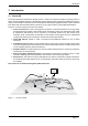
Table Of Contents
- 1 Glossary 5
- 2 Notices 6
- 3 Introduction 9
- 4 AIS AtoN product variants 13
- 5 Installation 14
- 6 Transceiver and Sensor Interface connections 19
- 7 Connecting external sensors and systems 23
- 8 Configuration using proAtoN 31
- 9 Operation 50
- 10 Data messages and data sources 51
- 11 Manual configuration 59
- 12 Technical specification 68
- 13 Firmware upgrade procedure 73
- 1 Glossary
- 2 Notices
- 3 Introduction
- 4 AIS AtoN product variants
- 5 Installation
- Figure 3 Typical AIS AtoN transceiver system connections
- Figure 4 Typical AIS AtoN transceiver and Sensor Interface system connections
- 1. Mount the Transceiver in a suitable location on the physical Aid to Navigation.
- 2. Install a VHF antenna according to the manufacturers instructions.
- 3. Install the supplied GNSS antenna.
- 4. Connect any sensor interfaces and light / RACON monitoring signals.
- 5. Connect power to the AIS AtoN transceiver and optional Sensor Interface.
- 6. Configure and commission the AIS AtoN transceiver and optional Sensor Interface via USB (note that this step can be carried out on shore prior to installation in a remote location).
- 5.1 What’s in the box (AIS AtoN transceiver)
- 5.2 What’s in the box (Sensor Interface)
- 5.3 Preparing for installation
- 5.3.1 Tools and wiring accessories
- 5.3.2 VHF antenna and cable
- 5.3.3 PC for configuration
- 5.4 Mounting the AIS AtoN transceiver and Sensor Interface
- 6 Transceiver and Sensor Interface connections
- 6.1 AIS AtoN transceiver connections
- 6.1.1 Power and USB connector
- 6.1.2 18 way Link connector
- 6.1.3 Using the 18 way link connector for direct connection of external equipment
- 6.1.4 VHF antenna connector
- 6.1.5 GNSS antenna connector
- 6.1.6 Earth connection stud
- 6.2 Sensor Interface connections
- 6.2.1 USB connector
- 6.2.2 Sensor 1 connector
- 6.2.3 Sensor 2 connector
- 6.2.4 Link connector
- 7 Connecting external sensors and systems
- 7.1 Connecting sensors and systems to the AIS AtoN Transceiver
- 7.1.1 Light ON/OFF interface
- 7.1.2 Light health interface
- 7.1.3 RACON status interface
- 7.1.4 AtoN Status source and configuration
- 7.1.5 NMEA0183 port
- 7.2 Connecting sensors and systems to the Sensor Interface
- 7.2.1 Isolated analogue inputs
- 7.2.2 Non-isolated analogue inputs
- 7.2.3 Light current sense loop
- 7.2.4 Isolated digital inputs
- 7.2.5 Non-isolated digital inputs/outputs
- 7.2.6 Isolated RS422 / NMEA0183 port
- 7.2.7 RS232 ports
- 7.2.8 SDI-12 interface
- 7.2.9 Relay drive output
- 7.2.10 Input voltage monitor
- 8 Configuration using proAtoN
- 8.1 proAtoN installation
- 8.2 Application layout
- 8.2.1 COM Port selection
- 8.2.2 Read / Write configuration
- 8.2.3 Transceiver configuration mode tabs
- 8.2.4 Sensor configuration mode tabs
- 8.2.5 Synchronisation status
- 8.2.6 Status bar
- 8.3 AIS AtoN transceiver configuration
- 8.3.1 Configuration of ‘Real’ AtoN parameters
- 8.3.2 Message schedule configuration
- Default messages
- Adding additional messages to the schedule
- Access scheme selection
- 8.3.3 FATDMA Schedule configuration
- Channel 1 start UTC
- Channel 1 start slot
- Channel 1 interval
- Channel 2 start UTC
- Channel 2 start slot
- Channel 2 interval
- Example FATDMA schedule
- 8.3.4 RATDMA Schedule configuration
- Channel 1 start UTC
- Channel 1 interval
- Channel 2 start UTC
- Channel 2 interval
- Example RATDMA schedule
- 8.3.5 Virtual AtoN configuration
- Virtual / Synthetic AtoN
- Virtual / Synthetic AtoN Details
- Virtual AtoN schedule
- 8.3.6 Status input configuration tab
- Current status (message 21)
- Light & RACON configuration
- Status bit source
- Status bit logic
- 8.3.7 Alert messages
- BIIT failure actions
- Vessel proximity alert
- Off position alert
- SART Relay Mode
- 8.4 Transceiver diagnostics
- 8.4.1 GNSS tab
- 8.4.2 Serial data tab
- 8.4.3 Diagnostics tab
- AtoN Details
- Power status
- Report generation
- Reported messages
- Active alarms
- 8.5 Sensor configuration
- 8.5.1 Sensor settings
- 8.5.2 ADC settings tab
- Light Current Sense group
- Current Sense ADC Scaling
- Voltage Measurement Scaling
- 8.5.3 Message settings tab
- Message #6 Configuration
- Message #8 Configuration
- 8.5.4 System information
- System Information
- Digital Input Status
- Sensor Health
- 8.5.5 Live data tab
- ADC Data
- 8.6 Other features
- 8.6.1 Offline configuration (applies to transceiver configuration mode only)
- 9 Operation
- 10 Data messages and data sources
- 10.1 Configurations without the Sensor Interface
- 10.2 Configurations with the Sensor Interface
- 10.2.1 AIS AtoN transceiver configuration
- 10.2.2 Configuration of the Sensor Interface
- 10.2.3 Accessing the Sensor Interface shell
- 10.2.4 General Sensor Interface configuration commands
- 10.2.5 Zeni Lite Message #6 configuration commands
- 10.2.6 ADC configuration commands
- 10.2.7 ADC Scaling
- 10.2.8 Message #6 Data Mapping
- 10.2.9 External device support
- 11 Manual configuration
- 11.1 Basic Type 1 AIS AtoN configuration (FATDMA operation)
- 11.2 NMEA0183 / IEC61162 configuration sentences
- 11.2.1 AAR - Configure broadcast rates for AtoN station
- 11.2.2 ACE - Extended general AtoN Station configuration
- 11.2.3 ACF - General AtoN Station configuration
- 11.2.4 AFB - Forced broadcast
- 11.2.5 AFC - AtoN function ID capability
- 11.2.6 AID - MMSI configuration
- 11.2.7 ARW -Configure the receiver turn-on times
- 11.2.8 MCR - Configure proprietary AtoN control
- 11.2.9 MPR - Message configuration of payload re-broadcast
- 11.2.10 TSP - Transmit slot prohibit
- 11.2.11 VER - Version
- 11.3 Proprietary configuration sentences
- 11.3.1 Status Bit Source
- 11.3.2 Status Bit Source Query
- 11.3.3 Light / RACON configuration
- 11.3.4 Light / RACON configuration query
- 11.3.5 General MCR query
- 12 Technical specification
- 12.1 Applicable equipment standards
- 12.2 AIS AtoN transceiver specification
- 12.2.1 Physical
- 12.2.2 Environmental
- 12.2.3 Electrical
- 12.2.4 GNSS
- 12.2.5 TDMA transmitter
- 12.2.6 TDMA receivers
- 12.2.7 Supported AIS messages (transmission)
- 12.2.8 Connector types
- 12.3 Sensor Interface specification
- 12.3.1 Physical
- 12.3.2 Environmental
- 12.3.3 Interfaces
- 12.4 Drawings and dimensions
- 13 Firmware upgrade procedure
- 1. Install and run the 'vxsend' utility (screenshot shown in Figure 33).
- 2. Click the Browse (…) button for the Image file, then navigate to and select the appropriate update file.
- 3. Select the COM port assigned to the AIS AtoN port or AIS AtoN Sensor port, depending on which element is being updated.
- 4. Click 'Start' and wait for the update to complete. Notification is given when the update has completed successfully.
- 5. Power cycle the transceiver and confirm normal operation before it is deployed.

Notices
Page 6
2Notices
When reading this manual please pay particular attention to warnings marked with the
warning triangle symbol shown on the left. These are important messages for safety,
installation and usage of the transceiver.
2.1 Safety warnings
2.2 General notices
2.2.1 Position source
All marine Automatic Identification System (AIS) transceivers utilise a satellite based location system such as
the Global Positioning Satellite (GPS) network. The general term for satellite based location systems is Global
Navigation Satellite System or GNSS. This manual refers to either GNSS or GPS depending on context.
2.2.2 Product category
This product is categorised as 'exposed' in accordance with the definitions provided in IEC 60945.
2.2.3 Disposal of the product and packaging
Please dispose of this product in accordance with the European WEEE Directive or with the applicable local
regulations for disposal of electrical equipment. Every effort has been made to ensure the packaging for the
product is recyclable. Please dispose of the packaging in an environmentally friendly manner.
2.2.4 Accuracy of this manual
This manual is intended as a guide to the installation, setup and use of this product. Every effort has been made
to ensure the accuracy of this manual, however due to continuous product development this manual may not
be accurate in all respects, therefore no guarantee is offered. If you are in any doubt about any aspect of this
product, please contact your supplier.
The part number and revision number of this manual are shown on the lower right hand corner of the front
cover.
!
This equipment must be installed in accordance with the instructions provided in this
manual. Failure to do so will seriously affect its performance and reliability. It is strongly
recommended that a trained technician installs and configures this product.
This equipment is intended as an aid to navigation and is not a replacement for proper
navigational judgement. Information provided by the equipment must not be relied upon as
accurate. User decisions based upon information provided by the equipment are done so
entirely at the users own risk.
!
!
The accuracy of a GNSS position fix is variable and affected by factors such as the antenna
positioning, how many satellites are used to determine a position and for how long satellite
information has been received.
!