
Cut Sheet


© 2016 Littelfuse Protection Relays & Controls
www.littelfuse.com/
Rev: 1-A-062716
Protection Relays
Current Monitoring Relays and Transducers
www.littelfuse.com/ecs
ECS SERIES
Description
The ECS Series of single-phase AC current sensors is a universal,
overcurrent or undercurrent sensing control. Its built-in toroidal
sensor eliminates the inconvenience of installing a stand-alone
current transformer. Includes onboard adjustments for current
sensing mode, trip point, and trip delay. Detects over or
undercurrent events like locked rotor, loss of load, an open heater
or lamp load, or proves an operation is taking place or has ended.
Operation
Input voltage must be supplied at all times for proper operation.
When a fault is sensed throughout the trip delay, the output
relay is energized. When the current returns to the normal run
condition or zero, the output and the delay are reset. If a fault is
sensed and then corrected before the trip delay is completed,
the relay will not energize and the trip delay is reset to zero.
Adjustment
Select the desired function, over or under current sensing.
Set the trip point and trip delay to approximate settings. Apply
power to the ECS and the monitored load. Turn adjustment and
watch the LED. LED will light; turn slightly in opposite direction
until LED is off. Adjustment can be done while connected to the
control circuitry if the trip delay is set at maximum. To increase
sensitivity, multiple turns may be made through the ECS’s
toroidal sensor. The trip point range is divided by the number of
turns through the toroidal sensor to create a new range. When
using an external CT, select a 2VA, 0-5A output CT rated for the
current to be monitored. Select ECS adjustment range 0. Pass
one secondary wire lead through the ECS toroid and connect
the secondary leads together.
Features & Benefits
FEATURES BENEFITS
Built-in toroidal
current sensing
Eliminates need to install stand alone
current transformer and provides isolation from
monitored circuit
Encapsulated Protects against shock, vibration, and humidity
Adjustable mode, trip
point and trip delay
Provides flexibility for use in many applications
10A, SPDT isolated
relay output
Allows control of loads for AC or DC voltages
Accessories
P1015-13 (AWG 10/12), P1015-64 (AWG 14/16),
P1015-14 (AWG 18/22) Female Quick Connect
These 0.25 in. (6.35 mm) female terminals are
constructed with an insulator barrel to provide
strain relief.
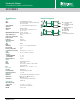
Wiring Diagram
V = Voltage
I> = Overcurrent
I< = Undercurrent
W = Insulated Wire Carrying
Monitored Current
Relay contacts are isolated.
Current Sensors
Ordering Information
See next page.