637f Servo drive Product Manual 07-02-10-01-E-V0505.
Additional Supporting Documentation UL:07-02-01 Product Manual Rack 6 U and EMV UL:07-02-02-01 Product Manual Power Supply Plug-in Module NE B UL: 07-02-09-02 Feedback System HIPERFACE® UL:07-02-10-02 Product - Manual Safe Standstill SBT UL:07-05-02-03 Product Manual SUCOnet K UL:07-05-03-02 Product Manual Bus Interface CAN for 635 / 637 / 637+ / 637f UL:07-05-04-02 Product Manual Bus Interface DP for 635 / 637 / 637+ / 637f UL:07-05-05-02 Product Manual Bus Interface Interbus S for 635 / 637 / 637+
Additional Supporting Documentation UL:07-09-04-02 Product Manual Suppression Aids EH UL:10-06-03 Product Manual Serial Transfer Protocol 635 / 637 / 637+ / 637f EASY- Serial UL: CD UL:10-06-05 EASYRIDER® Windows - Software Product Manual Software BIAS® UL: 12-01 Product Manual Accessories - Plugs UL:12-02 Product Manual Accessories - Cable UL:12-03 Product Manual Ballast Resistors ©SSD Drives GmbH. All rights reserved.
Table of Contents Seite The Most Important Thing First ........................................................................ 7 Safety Precation ................................................................................................. 8 1 General Information................................................................................ 10 1.1 1.1.1 1.1.2 1.1.3 1.1.4 1.2 1.2.1 1.2.2 1.2.3 1.3 1.3.1 1.3.2 1.3.3 1.3.4 1.3.5 1.3.6 1.4 1.4.1 1.4.2 System Description................................
Table of Contents Seite 3 Operating modes .................................................................................... 46 3.1 3.2 3.3 Operating modes and pin functions.............................................................................................. 47 Configurable pin-functions (depending on the operating mode) .................................................. 48 Function diagrams from inputs and outputs ..............................................................................
Table of Contents Seite 11 General Technical Data.......................................................................... 72 11.1 11.2 11.3 11.4 11.5 11.6 11.7 11.8 11.9 11.10 11.11 Power circuit ................................................................................................................................. 72 Control circuit ................................................................................................................................
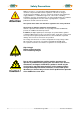
The Most Important Thing First The Most Important Thing First Thanks for your confidence choosing our product. These operating instructions present themselves as an overview of the technical data and features. Please read the operating instructions before operating the product. If you have any questions, please contact your nearest SSD Drives representative. Improper application of the product in combination with dangerous voltage can lead to injuries.
Safety Precautions Safety Precation Attention Digital servo drives, corresponding to EN 50178/VDE 0160, are power electronic components utilized for the regulation of the flow of energy in electrical power installations. They are exclusively designed and configured to supply SSD Drives, or SSD Drives approved, servo motors.
Safety Precautions Please observe! Pay Special Attention to the Following: Permissible Protection Class: Protective Grounding - operation is only permitted when the protective conductor is connected according to regulations. The operation of servo drives is not allowed, under the sole use of a residual current operated protective device as protection against indirect touching. The servo drive may only be used in the rack or in its compact enclosure.
1 General Information 1 General Information 1.1 System Description th The 5 generation of the digital servo drive serves to regulate the current, speed and position of AC servo motors, (standard: with resolver) All control circuits and functions are realized digitally. System variants Rack - version: 637f/D6R.... Compact - version: 637f/K D6R.... R Su pply volta ge: AC 1* oder 3 *230 VAC/50..60 Hz 3* 400... 460VA C/50 ..60H z R 637f/ K D6R Su pply volta ge: AC 1* oder 3 *230 VAC/50..
General Information 1 System Description 1.1.1 Digital Communication Diagnostics / Setup General: by 7 segment display Comfortable: via PC with EASYRIDER® Windows – Software from version V8.xx (serial interface RS232) Communication The serial-communication-protocol is open and fully documented. (Explanation see separate documentation) Every user has unrestricted access to all functions and parameters. ⌧ EASYRIDER ⌧ customer-made software ⌧ PLC So ftware 1.1.
1 General Information System Description 1.1.3 Compatibility with 637 Servo Drives (Not required for new projects) The 637f series servo drives are essentially pin- and functionally compatible with the servo drives 637. However, when a servo drive 637 is replaced with a 637f drive, the existing application must be checked and carefully tested to determine compliance under the corresponding safety precautions.
General Information 1.2 1 Modle code standard marking type: 637f/ optional a b c d e f g1 g2 h i X D6R XX .S5 -X -X -XXX -XXX -XXx -XXX marking a b c d e f special description XXXX/ K 0 D6R = = = = 02 04 06 10 16 22 30 .
1 General Information Modle Code 1.2.1 Combination possibilities for the various communications / I/O - modules Slots A B C Option modules 232 422 485 CAN 2CA 2C8 DEV SUC PDP IBS EA5 EAE SBT *2CA *2C8 Type Codel 637f/xD6Rxx.S5-x-x-232-000-xxx 637f/xD6Rxx.S5-x-x-232-EAE-xxx 637f/xD6Rxx.S5-x-x-232-SBT-xxx 637f/xD6Rxx.S5-x-x-232-2CA-xxx 637f/xD6Rxx.S5-x-x-232-2C8-xxx 637f/xD6Rxx.S5-x-x-422-000-xxx 637f/xD6Rxx.S5-x-x-422-EAE-xxx 637f/xD6Rxx.S5-x-x-422-SBT-xxx 637f/xD6Rxx.S5-x-x-422-2CA-xxx 637f/xD6Rxx.
General Information 1 Modle Code 1.2.2 Layout module slots Module slots: A -232 -422 -485 -CAN B -2CA -2C8 -DEV -SUC -PDP -IBS -EA5 C -EAE -SBT *-2CA *-2C8 Motor - Feedbacksysteme: -RD2: Standard resolver D -HF2: Option HIPERFACE® -SC2: Option rotor position transmitter * kann nur 1 mal CAN verwendet werden Note: The option modules of the slots A / B / C can only be reached after removing the cooling plate. 1.2.3 Layout of Power Board View solder side (solder jumper) JP2.8 JP2.3 JP2.7 JP2.
1 General Information 1.3 Range Data 1.3.1 Insulation Concept COM1 power - terminals customer part COM2 dep. Optionsmodule L1, L2, L3 Remote IN DC-bus M1, M2, M3 X10 analog brak - cirquit X10 digital X30 1) GND X40 Us power supply DC 24 V DC 24 V AC L1 N PE double insulation VDE 0160 Insulation of control voltage supply Take Care ! The insulation of control (Com1..
General Information 1 Range Data 1.3.3 Compact Units 637f/K D6R Compact Units 637f / Input Supply Voltage 50..60 Hz Phases Supply Peparation Power-On Current Limit Control Voltage Control Current incl. Fan Output Sine-Wave Voltage at Un De-rating of Unr Rated Current RMS Max. Current RMS Time for Imax Min. Motor Inductance (terminal / terminal) Brake Circuit Setpoint DC min. Un max. [V] [V] K D6R 02 .S5 -3 -7 K D6R 04 .
1 General Information Range Data 1.3.4 Plug-In Modules 637f/D6R Plug-In Modules 637f/ Input DC-BUS Rated Control Voltage Control Current 1) 2) Fan Output Sine-Wave Voltage at Un De-rating of Unr Rated Current RMS Max. Current RMS Time for Imax Min. Motor Inductance (terminal / terminal) Brake-Circuit Setpoint DC Continuous Rating Min. External Resistor General Power Loss Electronic Output Stage per A Weight Additional Data 2) D6R 04 .S5 -3 -7 D6R 06 .S5 -3 -7 min. Ug max.
General Information 1 Range Data 1.3.5 Single- and Three-Phase Supply Due to the line-ripple of the DC-Bus, the rate of usable output voltage is reduced as follows. This reduction affects the maximum attainable speed of the applied motor. Three-phase supply: The unloaded output voltage will be reduced to approx. 90%, maximally 85 % Single-phase supply: 50 – 60 Hz only servo drive 637f / ..
1 General Information Range Data 1.3.6 Output Power In case of continuous operation in the full-load range, the limits as shown in the following diagram need to be respected. Typical servo applications are not affected by this restriction. (S3 operation: Start/Stop).
General Information 1.4 Dimensions 1.4.1 Dimensions for Compact Device and Plug-In Module 1 Ø 5,2 fro nt side A B C D detail 18 D d Ø 10 243 220 400 262 386 plug -in modu le 233 304 spa ce for fan a Ø 5,2 d 1,6 280 detail 9 5,2 A B C D a 637f/K D6R 02...10 65,0 mm 60,0 mm 30,0 mm 14,5 mm 40,2 mm width 14 HP 8 HP 637f/K D6R 16...30 104,6 mm 100,0 mm 71,0 mm 14,5 mm 80,4 mm width 20 HP 1 HP ≈ 5,08mm 16 HP Important Note: You will need additional space on the front side, of approx.
1 General Information Dimensions 1.4.2 EMC-Clip (optional) 1.4.2.1 For 8 HP Drive side view front view 1.4.2.2 For 16 HP Drive side view front view EMC - Clip for Feedback cable (e.g.
Connector Assignments and Functions 2 2 Connector Assignments and Functions 2.1 General View of Connections for Compact Device 637f/ K D6R 02 – 10 2.1.1 637f/K D6R 02...10 Width 14 HP ________________________________________________________________________________________________________________________________________________________________________________________________________________________ 07-02-10-01-E-V0505.
2 Connector Assignments and Functions General View of Connections for Compact Device 637f/ K D6R 02 – 10 2.1.2 637f/K D6R 16...30 Width 20 HP ________________________________________________________________________________________________________________________________________________________________________________________________________________________ 24 Product Manual Type: 637f 07-02-10-01-E-V0505.
Connector Assignments and Functions 2.2 Connector Pin Assignments and Contact Functions 2.2.1 Power Connections for Plug-In Module 637f/D6R 2 (at the rear of the rack) (H15 multiple pin strip according to DIN 41612) ________________________________________________________________________________________________________________________________________________________________________________________________________________________ 07-02-10-01-E-V0505.
2 Connector Assignments and Functions 2.3 Signal Connections 2.3.1 Control Signal Plug X10 - SUB D25 Socket Complete Representation X10 Reference to pin 22 & pin 23: With controllers with option module SBT, kindly note the extended functions of these signals (see documentation 07-02-10-02-E-Vxxxx).
Connector Assignments and Functions 2 Signal Connections Control Signal Plug X10 - SUB D25 Socket Connection Example (without option SBT) drive side control signal plug X10 model: SUB D 25 spread out PLC +/- 10V 14 1 15 2 16 3 17 4 18 5 19 1) output ready 20 0V reference point, I/O-supply input active 21 1) N 8 10 23 11 - 24 spread out 25 2) L1 7 9 22 24V 0V + 6 12 13 +24V, I/O-supply ~ = PELVisolation mecanical limit switches L1 2) ~ = +24V (br) 0V (br) V1 N Sup
2 Connector Assignments and Functions Signal Connections Control Signal Plug X10 - SUB D25 Socket Inputs / Outputs Control Signal Plug X10 PIN X10 1 2 3 4 5 6 7 8 9 10 11 12 13 14 15 16 17 18 19 20 21 22 23 24 25 function type description shield connector configurable (chapter 3) stabilized auxiliary voltage -12VDC; max.
Connector Assignments and Functions 2.4 2 Feedback Sensor X30 The Feedback system generates a digital value, representing the rotor position Derivated from this value: commutation according to pole pair number actual speed value position value for position control 2.4.1 Function module X300 The connector X30 is directly related to the function module X300. This plug-in module (see chapter 1.4.3.1) determines the type of usable Feedback system.
2 Connector Assignments and Functions Feedback Sensor X30 2.4.
Connector Assignments and Functions 2.5 2 Multi-function X40 Description of the X40: Via a programmable I/O processor, the X40 connection can be configured differently. EASYRIDER® Windows - Software Standard functions: - Incremental output - Incremental input - Stepper motor - pulse inputs - SSI interface The unobstructed configurability provides ideal conditions for synchronous applications.
2 Connector Assignments and Functions Multi-function X40 2.5.1 Incremental Output EASYRIDER® Windows - Software X40 Mode = 0 Incremental encoder simulation for processing in positioning modules Standard: 1024 increments pulse duty cycle further selectable pulse numbers: 2048, 512, 256, 128, 64, 4096 Inr.
Connector Assignments and Functions 2 Multi-function X40 2.5.3 Stepper Motor Input pulse / direction EASYRIDER® Windows - Software X40 Mode = 2 Inr. I/O X40 PIN X40 1 2 3 4 5 6 7 8 9 2.5.4 Function Designation Output: Drive active inverted Output: Drive active Shield connector Pulse inverted Pulse Reference potential (generally to connect) /READY READY Schield /P P GND Direction inverted Direction Supply voltage output max.
2 Connector Assignments and Functions Multi-function X40 2.5.5 SSI Encoder Interface EASYRIDER® Windows - Software X40 Mode = SSI_13 bit Singleturn EASYRIDER® Windows - Software X40 Mode = SSI _14 bit Singleturn EASYRIDER® Windows - Software X40 Mode = SSI_25 bit Multiturn (13 bit Single- / 12 bit Multiturn) EASYRIDER® Windows - Software X40 Mode = SSI_26 bit Multiturn (14 bit Single- / 12 bit Multiturn) Inr.
Connector Assignments and Functions 2.6 Digital Interfaces 2.6.1 Service Interface - COM1 (RS232) 2 Standard Functions: Supporting all diagnosis and setup tasks Connection to your PC is made with the SSD Drives communication cable KnPC/D Communication is made via the SSD Drives operating program (EASYRIDER® Windows - Software) Com 1 RS232 Function drive side PIN RS232 PC side PIN 4-pin modular jack RXD TXD GND Type Code Kn PC 637f / 631-03.0 Kn PC 637f / 631-05.
2 Connector Assignments and Functions Digital Interfaces 2.6.2 Fieldbus Interface - COM2 Option modules SUB D09 socket Many different functions can be implemented by optional using of the option modules. Funktionen realisiert werden. Layout - see chapter 1.2.
Connector Assignments and Functions 2 Digital Interfaces 2.6.2.3 Module Designs Design A Design B Design C 2.6.2.4 Pin assignment for RS232 with option module RP 232 Pin 1 2 3 4 5 6 7 8 9 assignment as RS232 RXD TXD GND - 2.6.2.
2 Connector Assignments and Functions Digital Interfaces 2.6.2.6 Pin Assignment for CAN/DeviceNet with option module RP CAN / RP DEV / RP 2CA / RP 2C8, with galvanic isolation Pin description designation 1 2 CAN_L bus line (dominant low) CAN_L 3 4 5 6 7 Ground Optional ground CAN_H bus line (dominant high) - GND GND CAN_H 8 9 - 2.6.2.
Connector Assignments and Functions 2 Digital Interfaces 2.6.2.
2 Connector Assignments and Functions Digital Interfaces 2.6.2.
Connector Assignments and Functions 2 Digital Interfaces 2.6.2.
2 Connector Assignments and Functions Digital Interfaces 2.6.2.12 Pin assignment for I/O interface with option module RP 2C8, with galvanic isolation Digitale I/O Option X120B orr X120C Cage – Clamp terminal 10pole.. (min./max.
Connector Assignments and Functions 2 Digital Interfaces 2.6.2.12.
2 Connector Assignments and Functions 2.7 Option module RP SBT 2.7.
Connector Assignments and Functions 2 Option module RP SBT 2.7.2 Brake control and PTC evaluation Connector assignment X280 PIN X280 designation status 1 Supply for brake output and PTC evaluation Input 2 Reference point for supply Input 3 Reference point for Brake control 4 Brake control Active ok. 5 PTC Input 6 PTC Input Output Relais output Use of the Brake control The relay output X290.3 serves for the control of holding brakes.
3 Operating Mode 3 Operating modes The preselection of the device functions are carried out by choosing the operating modes 0...5 according to the following table, see chapter 3.1, (EASYRIDER® Windows - Software). Each operating mode allows the assignment of different in- and output functions (F0..F6). Operating mode Reference-source Hints for selecting the operating 0 1 2 analog (X10.5/18) switchable the operating modes 1 and 2 by input X10.
Operating Mode 3.1 3 Operating modes and pin functions 0 torque / speedcontrol 1 speed control operating modes 2 3 torque position / control speed-control input X10.14 F0, F1 F0, F1 F0, F1 input X10.15 F0, F1 F0, F1 input X10.4 --- input X10.25 input X10.11 Available pins number input X10.
3 Operating Mode 3.2 Configurable pin-functions (depending on the operating mode) Input functions (depending on the operating modes) input Nr. function F0 input X10.14 input X10.15 function F1 function F3 function F4 function F5 ⌧ 3) 1) move manually + limit switch + set selection data 20 ⌧ ⌧ ⌧ 3) 1) move manually limit switch - set selection data 2a ⌧ ⌧ input X10.4 latch input 1 input X10.25 latch input 2 input X10.11 start (slope 0->1) for BIAS move commands input X10.
Operating Mode 3.3 3 Function diagrams from inputs and outputs Pro te ctio n mo de s witc hing off Pro te ctio n mo de limiting acc. with EAS YR ID ER co nfig . me nue in acc. with EA SYR ID ER config.- menue Fa ult s ig nal / prote ctio n func tio n I 2t re gulator prote ction outp ut Warning(F0) X 10.20 /8/ outp ut Ready X 10.8 /3/ Warnin g time ap p rox. 3 sec. /3/ ma x.
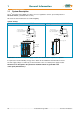
4 Mechanische Installation 4 Mechanical Installation 4.1 Mounting SSD Drives digital servo drives may be installed only in a vertical position to guarantee the best air circulation for the cooling ribs of the heat sink. Vertical installation above other drive racks or above other heat producing devices can lead to overheating. In addition the drives are to be operated exclusively in SSD Drives racks or the compact enclosure respectively. 4.
Electrical Installation 5 Electrical Installation 5.1 Safety 5 The voltages carried by power supply cables, motor cables, connectors, and certain parts of the drive can cause serious electric shocks and even death 5.2 The danger of electric shocks Caution ! Risk of electrical shock, wait 3 minutes after switching off, for discharging the capacitors. Disconnect SSD Drives plug-in units from mains before working on them.
5 5.6 Electrical Installation Fuses, contactors, filters Compact units Fuses, Contactors RCD-switch mains input currents mains protection protector-switch mains fuse Line filters general industrial env. max. motor cable 50m (EN55011 A) residential env. max. motor cable 20m (EN55011 B) industrial env. max. motor cable 50m (EN55011 A) residential env. max motor cable 20m (EN55011 B) industrial env. max. motor cable 20m (EN55011 A) residential env.
Electrical Installation 5.7 5 Correction of supply current Attention in case of continous load: Due to the capacitive input impedance of DC-Bus, the input current is deformated. This guides to RMS -values higher than the sinus-based calculated values. Fuses, contactors and line filters have to be selected in respect to this effect. In typical servo application with Stop/Go-operation (S3-Operation), the rating to nominal data will be sufficient.
5 Electrical Installation 5.8 Brake resistor 5.8.1 Selection of the brake resistor The energy of a moving system flows back to the Drive. The DC-Bus capacitors are able to take a small value. The rest has to be converted to heat by a resistor. Switching of this brake resistor depends on the DC-Bus voltage. The load of the resistor is simulated and supervised electronically (EASYRIDER® Windows - Software).
Electrical Installation 5 Brake resistor selection of the brake resistor Step 2 Example-Drive type Internal / external Brake-resistor required ? see data in chapter 1.3.3 / 1.3.4 637f/K D6R04-7 In case of unsufficient capability or not included internal Brake-Resistor, a type may be selected from the following list External and internal Brake-Resistors will be switched in parallel. The internal and external performance-Data may be added in this case. 5.8.2 acc. to data in 1.3.
5 Electrical Installation Brake resistor selection of the brake resistor Example: EASYRIDER Evaluation resistance value in use of internal and external resistances. Internal “Ballast resistances = 300 Ohm“ for ..KD6R10..-7 External “Ballast resistances = 100 Ohm“ for ..KD6R10..-7 formula : 1 1 1 = + Rtotal. R int . Rext. 1 1 1 = + ⇒ Rtotal. = 75Ω Rtotal. 300Ω 100Ω Set up resistance value = 75 Ohm Evaluation Ballst power in use of internal and external Ballast power.
Wiring Instructions 6 Wiring instructions 6.1 General Information 6 Digital servo drives are designed for operation in metallic grounded enclosures. For perfect operation as well as for observance of all regulations the front board must be connected with the enclosure electrically and fixed. 6.2 Control cabling Recommended cross section 0,25 mm².The control signal lines must be laid seperate from the power signal lines.(see chapter 6.7.
6 Wiring Instructions Electromagnetic compatibility (EMC) 6.7.1 A B C Hints for mounting All components are mounted inside of a steel control cubicle on a mounting plate (thickness min. 3mm). Recommended: Galvanizing 3mm The connection between drive housing filterhousing and mountig-plate must be blank and not reduced by varnish.
Wiring Instructions 6 Electromagnetic compatibility (EMC) 6.7.2 Example for mounting 6.7.3 Achieveable specifications and conditions Emissions: transmitted by cable or by air Interference immunity: (≅ radiation) transmitted by cable or by air Area Industrial Class A conditions additional conditions Motor-cable Standard length Area Class Standard EN50081-2/ see LNF S/E closed toroidal EN55011Klasse A chapter 5.
7 Setting and Programming 7 Setting and programming 7.1 Jumper All jumpers are set to a standard position in production ! Layout of the Jumpers see: Chapter 1.2.3 JP100, bridged pad... 2 and 3 (standard) 1 and 3 JP101, bridged pad... 2 and 3 (standard) 1 and 3 JP102, bridged pad... 2 and 3 (standard) 1 and 3 JP1, JP2 bridged pad... 2 and 3 (standard) 1 and 3 JP3, JP4 bridged pad... 2 and 3 (standard) 1 and 3 JP2.8, JP2.3 JP2.7, JP2.
Commissioning 8 8 Commissioning Caution ! Wiring errors or incompatible operation may cause unpredictable motions. Avoid danger for man and machine ! 8.1 Preparation For PC-link use the SSD Drives communication software EASYRIDER® Windows - Software. For the start, we suggest exercises in simulation mode to get familiar with EASYRIDER.This chapter presumes the knowledge how to handle EASYRIDER. Suggestions: Use test equipment to train yourself.
8 Commissioning 8.2 Commissioning in steps Step Action Remark 1 Before switching on Check the wiring, especially: Filter polarity, supply Motor wiring, motor polarity Resvolver wiring, polarity (or other feedback systems) 2 With critical mechanical part: remove motor shaft from application 3 Connect PC by RS232 link to the drive service port COM1 and start EASYRIDER ® 4 Set up state NOT ACTIVE avoid danger 7-segmentdispay 635/ 637/ 637+/ 637f 1) 631 X10.22 against X10.9 X10.
Commissioning 8 Commissioning in steps Step 11 Action Remark “ACTIVE” switched 7-segmentdispay 12 Adjust test generator as required. Activate test generator with “START F8”. Activate graph to display motor current or speed. Can be optimize manually (P- and I- gain) 13 Is the result ok? Yes: continue with 14 14 No: continue with U1 Preparation to the position controller The commissioning of the position controller is first recommended without linked mechanics.
8 Commissioning Commissioning in steps Step U1.1 Action Remark Menu: Tuning Speed Loop Stabile parameters are calculate bases on the system data; and can be called up with “Default value”. Sometimes it is recommended to make further manual tuning. Rated value can be soured either digital by the internal generator or analogue by 635/ 637/ 637+/ 637f +/- 10V at X10.5/18 U1.2 631 +/- 10V at X10.
Diagnosis and Trouble-Shooting 9 Diagnose und Fehlersuche 9.1 7-segment display 9 Many sources of faults can be narrowed down with the diagnosis display. display Output explanation servo drive 2) comment ready warning no display off off off off off off off off deactivated via input. on off deactivated via serial command. off off Active input is activated with switching on 24 V control voltage off off 631 635/637 637+ 637f X10.7 X10.22 X10.22 X10.
9 Diagnosis and Trouble-Shooting 7-segment display display Output explanation ready comment overload of the motor I²t servo drive 2) warning 1) 1) 1) 1) 1) 1) off off WARNING! Overload of the regulator I²t or motor I²t or temp.output stage too high. If no reaction within approx. 3sec.it switches off with signals /3/, /4/ or /5/.
Diagnosis and Trouble-Shooting 9 7-segment display display Output explanation ready comment X 300 – Module not inserted or wrong inserted or defect off servo drive 2) warning 631 635/637 637+ 637f X10.8 X10.14 X10.14 X10.14 X10.9 X10.15 X10.15 X10.15 X10.8 X10.9 X10.14 X10.15 X10.14 X10.15 X10.14 X10.
9 Diagnosis and Trouble-Shooting 7-segment display display Output explanation ready comment servo drive 2) warning 631 635/637 637+ 637f starting lockout RP SBT terminal X290. 3/4 check Max. speed overload check speed limits resp. setpoint speed CAN - Open 402 Sync Message error in Interpolated positioning mode 6.19c 8.
Diagnosis and Trouble-Shooting 9.2 9 Reset of a regulator trouble A general precondition for correct execution of the Reset is the elimination of the error cause. The error signals at blinking (BIAS) of the drive can be reset via: 1. Control voltage OFF/ON, 2. the serial command “Drive Reset“ 0x02 The host login must be occurred. The drive must be deactivated via the serial command “deactivate Drive“ 0x00. 3.
9 9.3 Diagnosis and Trouble-Shooting Trouble shooting The following list refers to faults which can occur during operation.
Block Circuit Diagram 10 10 Block circuit diagram ________________________________________________________________________________________________________________________________________________________________________________________________________________________ 07-02-10-01-E-V0505.
11 11 General Technical Data General Technical Data 11.1 Power circuit galvanic separation from control circuit specification in accordance with short circuit and to frame proof for overvoltage monitoring D6R..-3 in acc. with EN 50178 / VDE 0160 UL 508C and cUL Min. 2000 releasings overvoltage monitoring D6R..-7 Max. 765V DC ±10V DC min. 15V DC; configurable 95 ° C +/- 5% 4,75 kHz 9,5 kHz Max.
General Technical Data 11 11.4 Signal inputs and outputs, connection X120B resp. 120C additional galvanic separation from power and control circuit nominal voltage of the in- and outputs number of outputs signal outputs via OPTO coupler 24 V DC +20% / -10% 4 resistive load Imax. = 2A inductive loadmax. 1Henry Iout. Iout. 1A 1A 1A 1A 0,33A 0,33A 0,2A 0,2A Iout.
11 General Technical Data 11.6 Digitale communication RS232 - service interface COM1 19200 baud, 8 databits, 1 startbit, 1 stopbit, parity: even Optional RS232 / RS422 / RS 485 on SUB D – socket CAN1, Profibus DP, SUCOnet K on SUB D – socket Interbus S on SUB D – socket (OUT) Interbus S (Remote IN) CAN2 COM2 additional on SUB D – socket 11.
General Technical Data 11 11.9 Analog-Outps measuring pin X10.17 signal range resolution internal resistance -10V.....0.....+10V magnifier function can be normed 10 bit, independend of norming 1,8 kOhm measuring pin X10.6 signal range resolution internal resistance -10V.....0.....+10V magnifier function can be normed 8 bit, independend of norming 1,8 kOhm 11.10 Thermal data thermal data see chapter 1.3 11.11 Mechanical data dimensions weight see chapter 1.4 see chapter 1.
12 Disposal 12 Disposal The digital servo drive consists of different materials. The following table shows, which materials can be recycled and which have to be disposed of in a special way. material Metal plastics material printed board assembly recycle disposal yes yes no no no yes Dispose of the appropriate materials in accordance with the valid environmental control laws.
Software 13 13 Software 13.1 EASYRIDER® Windows - Software EASYRIDER® Windows - Software is an comfortable tool to use all drive functions. Detailed Online-Help-information’s and instruction are available.
13 Software 13.2 SSD Drives programming language BIAS In Operating mode 5 – Position control with BIAS, three user-defined programs can be executed parallel. The BIAS-program and the PLC-program (sequence cascades, 1 command per position controller sampling = 844 µs) as well as the Mathematics program (cyclic execution in remaining time of processor). The BIAS-program is primary intended for administration of travel commands.
Software 13 SSD Drives programming language BIAS The user has the possibility to program his sequence himself from this set of commands. Available program area Set number 0000 ... | ... | can be selected via ... | data inputs X10.xx ... | max. to block no. 63 and ... | and Strobe X10.2 ... | 0063 ... ... 1499 last block The BIAS operation set is listed on the next page.
13 Software 13.3 BIAS – Commands Position = const.
Certificates 14 14 Certificates ________________________________________________________________________________________________________________________________________________________________________________________________________________________ 07-02-10-01-E-V0505.
14 Certificates ________________________________________________________________________________________________________________________________________________________________________________________________________________________ 82 Product Manual Type: 637f 07-02-10-01-E-V0505.
Certificates 14 ________________________________________________________________________________________________________________________________________________________________________________________________________________________ 07-02-10-01-E-V0505.
14 Certificates ________________________________________________________________________________________________________________________________________________________________________________________________________________________ 84 Product Manual Type: 637f 07-02-10-01-E-V0505.
Certificates 14 ________________________________________________________________________________________________________________________________________________________________________________________________________________________ 07-02-10-01-E-V0505.
15 15 Index Index 7 E 7-segment display.............................................65, 66, 67, 68 EASYRIDER Instructions..................................................77 EASYRIDER® Windows - Software..................................77 election of the brake resistor ........................................55, 56 Electrical Installation .........................................................51 Electromagnetic compatibility (EMC) ...............................57 EMC Clip ..........................
Index 15 O S Operating modes................................................................ 46 Operating modes and pin functions ................................... 47 Operation configurations ................................................... 11 Option module RP SBT..................................................... 44 Option module RP SBT..................................................... 45 Output power..................................................................... 20 Safe Stop .........
16 16 Modification Record Modification Record Version Modification Chapter Date Name Comment V0103 V0204 text correction new functions connection X30 additional In-/Outputs Pin assignment for Interbus S correction safety module SBT Text addition for SBT 1.2 2.1-2.1.1 2.4.2 2.6.2.1 2.6.2.9 02.06.03 N. Dreilich new 7-segment display new BIAS commands SSD Drives diverse correction (text, design and photos) Model code, extended 9.1-9.2 13.
AUSTRALIA Eurotherm Pty Ltd Unit 1 20-22 Foundry Road Seven Hills New South Wales 2147 Tel: +61 2 9838 0099 Fax: +61 2 9838 9288 CANADA SSD Drives Inc 880 Laurentian Drive Burlington Ontario Canada, L7N 3V6 Tel: +1 905 333-7787 Fax: +1 905 632-0107 CHINA Eurotherm Pty Ltd Apt.