
Data Sheet
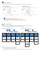

CIRCUIT DIAGRAMS
In order to suit any application, these sensors have been designed with various output circuit configurations.
CAUTION: Take care when connecting loads.
The minimum load impedance should not exceed Vs/max output current.
Note: Shorting the output to Vs or 0V will result in irreparable damage to the sensor.
ORDER INFORMATION
Generate your specific part number using the convention shown opposite. Use only those letters and numbers that
correspond to the sensor and output options you require — omit those you do not.
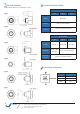
Sensor mounted from inside vessel Sensor mounted from outside vessel
Notes:
Type 3 and Type 5 sensors are mounted internally.
Types 1, 2, 6 & 7 sensors are mounted externally.
SH suffix applicable to Types 1, 2, 6 & 7 sensors only; omit from Type 3 and Type 5 sensor part numbers.
Housing
Material
Housing
Type
Operating
Temp.
Output
Logic
C
Polysulfone
1
Type 1
M12x1-8g
0
-25 °C
to +80°C
Blank
Output
High in air
T
Trogamid®
2
Type 2
M12x1-8g
1
-40 °C
to +125°C
L
Output
Low in air
6
Type 6
1/2”-20 UNF
P
PWM output
7
Type 7
1/4” NPT
L L X X X
0 D 3
X
S H
L L
X X X
0 D 3
X
Housing
Material
Housing
Type
Operating
Temp.
Output
Logic
C
Polysulfone
3
Type 3
M12x1-8g
0
-25 °C
to +80°C
Blank
Output
High in air
T
Trogamid®
5
Type 5
M10x1
1
-40 °C
to +125°C
L
Output
Low in air
P
PWM output