
User's Manual


4 of 7
MSAN
-
00
9
K-Band Miniature Doppler Transceiver Module
Application Note
V1
.
0
0
ST Electronics (Sa
tcom & Sensor Systems) Pte Ltd
1 Ang Mo Kio Electronics Park Road, #06-02, ST Engineering Hub, Singapore 567710
Tel: (65) 6521 7888 Fax: (65) 6521 7801 Email: info@agilsense.com
Website: www.agilsense.com ( Regn. No.: 199103901W )
7. Output Signals
Doppler shift - Doppler signal appears at IF terminal when movement is detected. The magnitude of
the Doppler signal is proportional to the reflection of transmitted energy and is typically in the range of
microvolts (µV). A high-gain low-frequency amplifier is usually connected to the IF terminal in order
to amplify the Doppler shift to a processable level. The frequency of Doppler shift is proportional to
velocity of motion. Typical human walking generates Doppler shift below 100 Hz. Doppler frequency
can be calculated by Doppler equation in Annex 2.
The Received Signal Strength (RSS) is the voltage measured at the IF output, when the module is
subjected to a motion. Reflection of a human body is dependent on the size of the body, clothing,
apparels and other environmental factors. RSS measured for different human bodies may vary by as
much as 50%.
Circuit designer must take note of the typical Received Signal Strength (RSS) specified in technical
data sheet, when designing the amplifier. Sensitivity deviation between modules has to be considered
when setting amplifier gain or alarm threshold. On-production gain adjustment may be necessary if a
narrow window for triggering threshold is required.
Noise - The noise specified in the technical data sheet is the noise measured in an Anechoic chamber,
that shields the unit-under-test from external interference, as well as reflection from surfaces. Hence,
the figure is only presenting the noise generated by the internal circuit itself.
In actual applications, besides noise generated from internal electronic circuit, other noises may be
picked up from surrounding, or other part of the electronic circuit. Special attention has to be given to
the interference pick-up from fluorescent light, as the 100/120 Hz noise is closed to the Doppler
frequency generated by human movement. On and off switching of certain devices (relay, LED, motor,
etc.) may generate high magnitude of transient noise at the IF terminal. Careful PCB layout and time-
masking is necessary to prevent false triggering.
DC Level - DC level (0.01 to 0.2 Vdc) exists at the IF terminal and its polarity can be positive and
negative. Its magnitude may vary over temperature. AC coupling is recommended for IF terminal
connection.
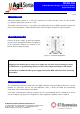
8. Placing the module in enclosure
If AP9 series module needs to be housed in an enclosure, it is important to ensure that the performance
of the module is not significantly degraded by the presence of enclosure.
The recommended material for the enclosure is plastic (such as ABS), as microwave can penetrate
through the material without significant loss. For comparison purpose, a metal results in full reflection
while water results in high absorption of the microwave. It is therefore important not to use any metallic
material as the enclosure.