
User's Manual


2 of 6
DF100-0
K-Band Doppler RF Transceiver Module
Users Manual
4. Using ENABLE (pin 1)
When this pin is driven LOW (GND), this will activate the DRO and hence transmit the signal.
On the other hand, when it is driven HIGH (typically +5V), the DRO will be de-activated. This
feature can be used to reduce power consumption by introducing pulse to this pin.
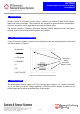
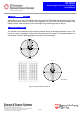
5. Radiation Pattern
The module to be mounted with the antenna patches facing to the desired detection zone. The
user may vary the orientation of the module to get the best coverage. The radiation patterns of
the antenna and their 3dB beamwidth are shown in below diagram.
E-plane
-35 -30 -25 -20 -15 -10 -5 0
-35
-30
-25
-20
-15
-10
-5
0
-35-30-25-20-15-10-50
-35
-30
-25
-20
-15
-10
-5
0
0
30
60
90
120
150
180
210
240
270
300
330
H-plane
-35 -30 -25 -20 -15 -10 -5 0
-35
-30
-25
-20
-15
-10
-5
0
-35-30-25-20-15-10-50
-35
-30
-25
-20
-15
-10
-5
0
0
30
60
90
120
150
180
210
240
270
300
330
Figure 3: Beam pattern of DF100-0
Elevation
Azimuth