
User's Manual


12 of 16
MSAN
-
008
K-Band FMCW Transceiver DF Modules
Application Note
V1.0
1
ST Electronic
s (Satcom & Sensor Systems) Pte Ltd
1 Ang Mo Kio Electronics Park Road, #06-02, ST Engineering Hub, Singapore 567710
Tel: (65) 6521 7888 Fax: (65) 6521 7801 Email: info@agilsense.com
Website: www.agilsense.com ( Regn. No.: 199103901W )
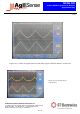
There are two output signals in DF9 series: I and Q signal. As the figures shown, amplitude of output
signal becomes smaller when distance increases, while the frequency of output signal increases with
distance. When the distance of detected object is small enough, frequency difference of transmitted and
received signal will be equal or even less than sweeping frequency. In that case, user may not be able to
isolate frequency difference from sweeping frequency.
The minimum detection range for DF9 series will be:
B
c
R
2
Where
c: speed of light in freee space, 3*10
8
m/s
B
: frequency sweeping bandwidth.
Reader may also notice the phase difference between I and Q signals. Ideally, there is a 90 degree phase
difference between I and Q signals. By identifying phase lagging/leading, information of movement
direction can be determined.
9. Placing the module in enclosure
As the applications of DF series are mostly in traffic (outdoor), it is inevitable that the module needs to
be housed in an enclosure. As such, it is important to ensure that the performance of the module is not
significantly degraded by the presence of enclosure.
The recommended material for the enclosure is plastic (such as ABS), as microwave can penetrate
through the material without significant loss. For comparison purpose, a metal results in full reflection
while water results in high absorption of the microwave. It is therefore important not to use any metallic
material as the enclosure.
Figure 13:
I and Q signal with target
detected at 5m away