
User's Manual


13 of 16
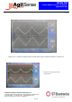
MSAN
-
008
K-Band FMCW Transceiver DF Modules
Application Note
V1.0
1
ST Electronic
s (Satcom & Sensor Systems) Pte Ltd
1 Ang Mo Kio Electronics Park Road, #06-02, ST Engineering Hub, Singapore 567710
Tel: (65) 6521 7888 Fax: (65) 6521 7801 Email: info@agilsense.com
Website: www.agilsense.com ( Regn. No.: 199103901W )
It is recommended that the cover placed in front of the DF antenna is of flat panel, so that the beam
width of the antenna is not significantly distorted. The thickness of the cover, h
1
and the spacing between
the antenna and the cover, h
2
should be ideally half-wavelength of the microwave signal.
In this case, for DF series module whose transmission frequency is ~24GHz, the recommended h
1
and h
2
are 3-4mm and 6mm.
A half wavelength of a 24 GHz in the air is about 6mm. However, the half wavelength of the signal in
other medium depends on the dielectric constant of the material. In the case of ABS which has a
dielectric constant of between 2.5 to 3.5, the half wavelength of the signal is 3 – 4 mm.
Figure 14: Recommended thickness and clearance for ABS placed in front of DF sensor
10. Using EN (pin 1)
EN (pin 1) can be used to control the oscillator. The internal voltage source is supplied to the oscillator
via a PNP transistor switch. When EN is asserted LOW (GND), the switch is on and internal voltage is
supplied to the oscillator, resulting in a transmission of 24GHz microwave signal. On the other hand,
when it is driven HIGH (+3.3V or higher), the oscillator is de-activated. The current drawn from the EN
pin is typically less than 1mA, and hence, it can be driven by TTL or CMOS as long as the voltage high
is +3.3V or more.
This feature can be used to reduce power consumption by introducing pulse to this pin.
Figure 15: Internal circuit of EN function in DF sensor
h
1
~ 3
-
4 mm
h
2
~ 6mm
ABS
DF unit