
User's Manual


7 of 16
MSAN
-
008
K-Band FMCW Transceiver DF Modules
Application Note
V1.0
1
ST Electronic
s (Satcom & Sensor Systems) Pte Ltd
1 Ang Mo Kio Electronics Park Road, #06-02, ST Engineering Hub, Singapore 567710
Tel: (65) 6521 7888 Fax: (65) 6521 7801 Email: info@agilsense.com
Website: www.agilsense.com ( Regn. No.: 199103901W )
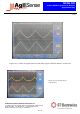
6. Radiation Pattern
The module to be mounted with the antenna patches facing to the desired detection zone. The user may
vary the orientation of the module to get the best coverage. The radiation patterns of the antenna and
their 3dB beam width are shown in below diagram.
E-plane
-35 -30 -25 -20 -15 -10 -5 0
-35
-30
-25
-20
-15
-10
-5
0
-35-30-25-20-15-10-50
-35
-30
-25
-20
-15
-10
-5
0
0
30
60
90
120
150
180
210
240
270
300
330
H-plane
-35 -30 -25 -20 -15 -10 -5 0
-35
-30
-25
-20
-15
-10
-5
0
-35-30-25-20-15-10-50
-35
-30
-25
-20
-15
-10
-5
0
0
30
60
90
120
150
180
210
240
270
300
330
Figure 6: Beam pattern of DF990
Elevation
Azimuth