
User's Manual


3 of 7
X
-
Band Microwave Motion Sen
sor Module
HB170 Users Manual
V1.0
0
ST Electronics (Satcom & Sensor Systems) Pte. Ltd.
29 New Industrial Road, ST Electronics Paya Lebar Building, Singapore 536213
Tel: (65) 6521 7888 Fax: (65) 6521 7333 Email: agilsense@stee.stengg.com
Website: www.ag
ilsense.com (
Regn
:
199103901W
)
5. Transmit Frequency
The transmit frequency and power of the module is set by the factory. There is no user adjustable part in
this device.
The module is a low power radio device (LPRD) or intended radiator. Local radio communication
authority regulates use of such a device. Though user license may be exempted, type approval of
equipment or other regulation compliance may be required.
Annex 1 shows the allocated frequency in some countries.
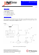
6. Radiation Pattern
The module is to be mounted with the antenna patches facing to the desired detection zone. The user
may vary the orientation of the module to get the best coverage. The radiation patterns of the antenna
and their half power beam width (HPBW) are shown in below diagram.
7. Output Signals
Doppler shift – The IF terminal outputs a Doppler shift signal when movement is detected. The
magnitude of the Doppler Shift is proportional to the reflection of the transmitted energy and is in the
range of microvolts (µV). A high gain low frequency amplifier is usually connected to the IF terminal
in order to amplify the Doppler shift to a processable level (see Annex 2). Frequency of Doppler shift is
proportional to velocity of motion. Typical human walking generates Doppler shift below 100 Hz.
Doppler frequency can be calculated by Doppler equation in Annex 2.
The Received Signal Strength (RSS) is the measured voltage of the Doppler shift at the IF output. The
RSS figure specified in the technical data sheet is the level of a 25 Hz Doppler shift, generated from the
modulated microwave signal received at the receiver antenna, The received microwave signal is
attenuated to 93 dB below the transmit microwave signal from the transmit antenna of the same unit.
Azimuth
Azimuth
Elevation