
User's Manual


3 of 8
X
-
Band
FSK
Microwave Motion Sensor
m
odule
HB180 Users Manual
V1.0
0
ST Electronics (Satcom & Sensor Systems) Pte. Ltd.
29 New Industrial Road, ST Electronics Paya Lebar Building, Singapore 536213
Tel: (65) 6521 7888 Fax: (65) 6521 7333 Email: agilsense@stee.stengg.com
Website: www.agilsense.com (
Regn
:
199103901W
)
5. Transmit Frequency
The transmitter’s center frequency and power of the module are set by the factory. There is no user
adjustable part in this device.
The module is a low power radio device (LPRD) or intended radiator. Local radio communication
authority regulates use of such a device. Though user
license may be exempted, type approval of equipment
or other regulation compliance may be required.
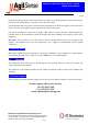
6. FM Characteristics
The HB180 module’s electric tuning voltage range:
+0.5~5V, and the typical electric tuning sensitivity
(avg.) is -1MHz/V. The typical FM linearity is ±10%.
Figure4: Typical VCO characteristics
Annex 1 shows the allocated frequency in some countries.
7. Radiation Pattern
The module is to be mounted with the antenna patches facing to the desired detection zone. The user
may vary the orientation of the module to get the best coverage. The radiation patterns of the antenna
and their half power beam width (HPBW) are shown in below diagram.
Azimuth
Azimuth
Elevation