
Technical Specs
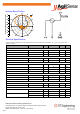
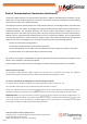
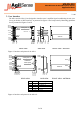
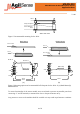
Table Of Contents

4 of 8
MSAN-010
AP11 Miniature K-Band Microwave Sensor
Application Note
V1.00
To ensure functionality of the sensor module, users are advised to prevent any metallic parts from
contacting +V and IF terminals, or mounted too close to the patch antenna array.
Any pressure or stress to the module should be avoided as it may result in performance variations.
GND
IF
V+
GND
2.54
13.60
R1.80
2
R1.65
2
19.70
PCB cavity
GND
IF
V+
GND
2.54
PCB cavity
GND
20.70
6.10
23.10
6.80
1.80
User's interface
PCB
AP11-S
User's interface
PCB
AP11-S
Back Mount Bottom Mount
(a) (b)
Figure 6. Mounting options and recommended PCB footprint for the AP11-S. (a) Back Mount (b)
Bottom Mount.
AP11 Side View
User's interface
PCB
3-way receptacle
AP11
Figure 5. Recommended mounting for the AP11.