
User's Manual


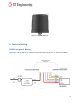


Table Of Contents
- 1. Street Lighting Control
- 2. LCU NEMA model LCUN35G
- 3. Safety Instructions
- 4. Technical Data
- 5. Electrical wiring
- 6. Standards Compliance
- 7. Regulation Information
- 8. Installation Overview
- 8.1 Installation with the GPS Component
- 8.2 Installation without the GPS components
- 8.2.1 CSV file
- 8.2.3 Installation
- 9. Installing the LCU NEMA
- 10. Post-Installation Commissioning
- 11. Contact Details
- A. Appendix - About GPS Coordinate Formats
- B. Appendix - Commissioning CVS File

ST Engineering Telematics Wireless Ltd
9
Figure 4 - LCU NEMA 7-Pin Contact Interface
LCU NEMA Contact Details
LCU NEMA Pinout
#
Wire Color
Name
Purpose
1
Black
Li
AC Line In
2
White
N
AC Neutral
3
Red
Lo
AC Line Out: Load
4
Violet
Dim+
DALI(+) or 1-10V(+) or PWM(+)
5
Gray
Dim-
Common GND: DALI(-) or 1-10V(-)
6
Brown
Reserved 1
Dry Contact Input or serial communication
7
Orange
Reserved 2
Output Open Drain or serial communication
LED Driver
Model
Pin 1-2
Black-White
Pins 3-2
Red-White
Pins 5-4
Gray-Violet
Pins 6-7
Brown-Orange
NEMA 7-pin
Main AC Line IN
Main AC Neutral IN
AC for lamp Line
OUT
Neutral IN
Dimming – 1-10V
Analog, DALI, PWM,
Digital input – Dry
contact, output
open drain,
Serial
communication