
User's Manual
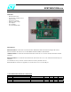

SPBT2425C2DB.xxx
rev. 1.0 18-Jun-07 2/9
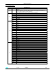
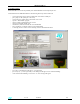
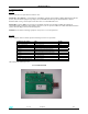
2 - I/O CONNECTIONS
DESCRIPTION
J1 Vcc Power supply plug ( 5V )
J2
USB Port
When the USB port is connected , the 5V USB is used to supply the BT module ( by
means a voltage regulator) and the board itself
When USB port is used 5V on J1 power plug can be avoided
1 USB_DN
2 USB_DP
3 SPI_FRM
4 SPI_CLK
5 SPI_TXD
6 SPI_RXD
J3
7 GND
1 Boot
2 GPIO 0
3 GPIO 1
4 GPIO 2
5 GPIO 3
6 GPIO 4
7 GPIO 5
8 GPIO 6
9 GPIO 7
10 GPIO 8
11 GPIO 9
12 LP_CK
13 GPIO 11
14 GPIO 12
15 GPIO 13
16 GPIO 14
17 GPIO 15
18 1.8V
19 2.8V
20 INHIBIT
J4
21 VDD
1 RX_EN
2 PA_EN
3 PA_V1
4 PA_V0
5 ANT_SW
6 PCM_A
7 PCM_B
8 PCM_SYNC
9 PCM_CLK
10 NTRST
11 TDI
12 TMS
13 TCK
14 TDO
15 13 MHz out
16 RESET
17 INT2
18 RXD
19 TXD
20 I2C0
J5
21 I2C1