SPSGRFC Sub1GHz (433 or 868 or 915 MHz) programmable transceiver module Preliminary Datasheet Features Programmable Radio features - Modulation schemes: 2-FSK, GFSK, MSK, GMSK, OOk, ASK Air data rate from 1 to 500 kbps On board UFL connector for external antenna Operating temperature range from -40 °C to 85°C RF features - Receiver sensitivity: -118 dBm Programmable RF output power up to +16 dBm Preliminary module picture 11.5 mm x 13.5 mm x 2.
SPSGRFC 1 Description The SPSGRFC is an easy to use Sub1GHz transceiver module, with many programmable features. The module provides a complete RF platform in a tiny form factor. The SPSGRFC enables electronic devices with wireless connectivity, not requiring any RF experience or expertise for integration into the final product. The SPSGRFC, being a certified solution, optimizes the time to market of the final applications.
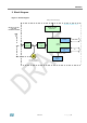
SPSGRFC 3 Block Diagram Figure 1 – Block Diagram Battery or External Supply SPSGRF-xxx Module - 2016 868 MHz or 915 MHz or 433 MHz EXTERNAL ANTENNA SUPPLY FILTER Bead Ferrite RF TUNING NETWORK RF BALUN + Filter Host Controller interface SPI LINE Programmable I/O I/O SPIRIT1 DEVICE M.C.U. clock 50 MHz Crystal UFL RF connector for external antenna Rev 0.
SPSGRFC 4 Short description of the module functional behaviour The SPIRIT1 device inside the SPSGRFC module is provided with a built-in main controller which controls the switching between the two main operating modes: transmit (TX) and receive (RX). In shutdown condition the SPSGRFC module can be switched on/off with the external pin SDN, all other functions/registers/commands are available through the SPI interface and GPIOs.
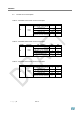
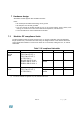
Hardware Specifications General Conditions (VIN= 3.3V and 25°C) 5.1 Absolute Maximum Ratings Table 1 - Absolute Maximum Ratings Rating Storage temperature range Min -40 Typical - Max +85 Unit °C Supply voltage, VIN -0.3 - + 3.9 Volts I/O pin Voltage -0.3 - + 3.9 Volts - 10 - dBm RF saturation input power 5.
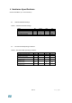
SPSGRFC 5.3 Module current consumption Table 3 – SPSGRFC-433 module current consumption Symbol Idd Parameter Supply current Test conditions Operating mode Tx, +11.6 dBm, 2-FSK, 433 MHz Operating mode Tx, -7 dBm, 2-FSK, 433 MHz Operating mode Rx, 433 MHz Max Unit 22 mA 9 mA 10 mA Command mode Shutdown high level Vdd With other I/O in High impedance 0.6 mA 0.
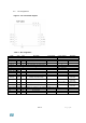
5.4 Pin Assignement Figure 3 – Pin connection diagram Table 6 – Pin Assignment Name Type Pin # Description ALT Function V max. Tolerant Initial State SPI Interface SPI_CLK I 7 SPI CLOCK (Max. 8 MHz) Vin SPI_MISO O 8 SPI MISO (MASTER in / SLAVE out) Vin SPI_MOSI I 9 SPI MOSI (MASTER out SLAVE in) Vin SPI_CS I 10 SPI “Chip Select” (SPI slave select) Vin (1.8V + 3.6V max.) Power and Ground Vin 5 Vin GND 6 GND 11 SHUTDOWN input (active high) (1.8V + 3.6V max.).
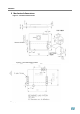
SPSGRFC 6 Mechanical dimensions Figure 4 – Mechanical Dimensions Figure 5 – Recommend land pattern Page |8 Rev 0.
7 Hardware design SPSGRFC module supports SPI hardware interfaces. Notes All unused pins should be left floating; do not ground. All GND pins must be well grounded. The area around the module should be free of any ground planes, power planes, trace routings, or metal for 6 mm from the module antenna position, in all directions. Traces should not be routed underneath the module. 7.
SPSGRFC 8 Module user firmware short description For more user firmware information, please refer to the SPIRIT1 Datasheet - October 2016 DocID022758 Rev 10. Downloadable at the following link: www.st.com/resource/en/datasheet/bluenrg-1.pdf The following are short firmware notes, useful to furnish to the user a condensed view of the many programming ways of the SPSGRFC-xxx module.
Rev 0.
SPSGRFC P a g e | 12 Rev 0.
Rev 0.
SPSGRFC P a g e | 14 Rev 0.
Rev 0.
SPSGRFC P a g e | 16 Rev 0.
Rev 0.
SPSGRFC P a g e | 18 Rev 0.
Rev 0.
SPSGRFC P a g e | 20 Rev 0.
Rev 0.
SPSGRFC P a g e | 22 Rev 0.
Rev 0.
SPSGRFC P a g e | 24 Rev 0.
Rev 0.
SPSGRFC P a g e | 26 Rev 0.
Rev 0.
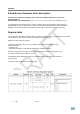
SPSGRFC 9 Regulatory compliance RF compliance The RF certifications obtained are described in Table 8 below. Table 8.
For the SPSGRFC-915 module the approved antenna is the TAOGLASS TI.19.2113 *Note all data provided in this table are based on the “TAOGLASS TI.19.2113” reference documentation. Rev 0.
SPSGRFC For the SPSGRFC-868 module the approved antenna is the LINX ANT-868-CW-QW *Note all data provided in this table are based on the “LINX - ANT-868-CW-QW ” reference ground plane. P a g e | 30 Rev 0.
For the SPSGRFC-433 module the approved antenna is the LINX ANT-433-CW-QW *Note all data provided in this table are based on the “LINX - ANT-433-CW-QW ” reference ground plane. Rev 0.
SPSGRFC FCC and IC This module has been tested and complies with the FCC part 15 and IC RSS-247 regulations. These limits are designed to provide reasonable protection against harmful interference in approved installations. This equipment generates, uses, and can radiate radio frequency energy and, if not installed and used in accordance with the instructions, may cause harmful interference to radio communications.
CE compliance This module complies with the following European EMI/EMC and safety directives and standards: – ETSI EN 300 328 V1.8.1:2012 – EN 301 489-1 V1.9.2:2011 + EN 301 489-17 V2.2.1:2009 – EN 60950-1:2006 + A11:2009 + A1:2010 + A12:2011 + A2:2013 – EN 62479:2010 Figure 3. CE certified Rev 0.
SPSGRFC 10 Reflow soldering The SPSGRFC is a surface mount Sub1GHz Transceiver module supplied on a 11 pin, 4-layer PCB. The final assembly recommended reflow profiles are indicated here below. Soldering phase has to be executed with care: In order to avoid undesired melting phenomenon, particular attention has to be taken on the set up of the peak temperature. Here following some suggestions for the temperature profile based on IPC/JEDEC J-STD-020C, July 2004 recommendations.
11 RoHS compliance ST Bluetooth modules comply with the ECOPACK2 level of RoHS compliance grade.
SPSGRFC Déclaration de conformité A.1 Certification FCC Le module SPSGRFC-915 a été testé et déclaré conforme avec la section 15 de la Règlementation FCC. Ces limitations sont stipulées afin de procurer une protection raisonnable contre les interférences gênantes dans les installations approuvées.
A.1.2 Instructions pour l’utilisation du produit La présente section concerne les produits finis contenant le module SPSGRFC-915, assujettis aux normes FCC. Le manuel du produit final doit contenir la déclaration suivante (ou une mention analogue que recouvre la même notion): “ Avertissement: Les changements ou modifications non expressément approuvés par la partie responsable de la conformité pourraient annuler l'autorisation de l'utilisateur de faire fonctionner cet équipement. (Section 15.
SPSGRFC A.2 Certification IC (a) Le module SPSGRFC-915 a été testé et déclaré conforme avec la Règlementation IC CNR-210. Ces limitations sont stipulées afin de procurer une protection raisonnable contre les interférences gênantes en installations approuvées. Cet appareil génère, utilise et diffuse des ondes radio et, s’il n’est pas installé et utilisé en conformité avec les instructions dont il fait l’objet, peut causer des interférences gênantes sur les communications radio.
A.2.2 Instructions pour l’utilisation du produit La présente section concerne les produits finis contenant le module SPSGRFC-915, assujettis aux normes IC. Le manuel du produit final doit contenir la déclaration suivante (ou une mention analogue que recouvre la même notion): “Avertissement: Les changements ou modifications non expressément approuvés par la partie responsable de la conformité pourraient annuler l'autorisation de l'utilisateur de faire fonctionner cet équipement.
SPSGRFC A.3 Certification CE Le module SPSGRFC a obtenu une certification de conformité aux normes suivantes: – EN 300 328 V1.8.1 :2012 – EN 300 328 V1.9.1 :2015 – EN 301 489-17 V2.2.1 :2009 – EN 301 489-1 V1.9.2:2011 – EN 62479 :2010 – EN60950-1:2006 + A11:2009 + A1:2010 + A12:2011 + A2 :2013 Le module est certifié CE: P a g e | 40 Rev 0.
A.4 Antennes certifiées Pour le module SPSGRF-915 l'antenne approuvée est le Taoglas TI.19.2113 TI.19 est un 915MHz bande ISM dipôle antenne omnidirectionnelle haute performance. La conception permet à l'antenne articulée à être positionnée le plus approprié à son angle. Cette antenne dispose d'un SMA (M) de connecteur Fiche.
SPSGRFC Pour le module SPSGRF-868 l'antenne approuvée est le LINX ANT-868-CW-QW Les antennes CW série ¼ d'onde offrent exceptionnelle la performance dans un boîtier robuste et esthétiquement attrayant. Ces antennes sont disponibles avec SMA standard ou FCC Part 15 conformes connecteurs RP-SMA. connecteurs RP-SMA permettent le remplacement facile sur le terrain tout en respectant les exigences de la FCC. Une grande variété de connecteurs correspondant permet de nombreuses options de montage.
Caractéristiques • À bas prix • Performance excellente • modèle Omni-directionnel • Large bande passante • Très faible ROS • Entièrement intempérisés • arbre principal flexible • Robuste et résistante aux dommages • SMA ou de la partie 15 connecteur RP-SMA conforme • Utiliser avec du plastique * ou boîtiers métalliques * Nécessite la proximité plan de masse Spécifications électriques Fréquence Centre: 868MHz Recom. Fréq. Gamme: 750-950MHz Wavelength: ¼ d'onde Gain de crête: 1.6dBi ROS: <1,9 typ.
SPSGRFC Pour le module SPSGRF-433 l'antenne approuvée est le LINX ANT-433-CW-QW P a g e | 44 Rev 0.
Spécifications électriques Fréquence Centre: 433MHz Recmd. Fréq. Gamme: 400-470MHz Wavelength: ¼ d'onde Gain de crête: 3.3dBi ROS: <1,9 typ. au centre Impédance: 50 ohms Connecteur: RP-SMA ou SMA Oper. Temp. Plage: -40 ° C à + 90 ° C Caractéristiques électriques et les parcelles mesurées sur 10,16 cm x 10,16 cm (4,00 "x 4,00") plan de masse de référence Informations de commande ANT-433-CW-QW (avec connecteur RP-SMA) ANT-433-CW-QW-SMA (avec connecteur SMA) Rev 0.
SPSGRFC Please Read Carefully: Information in this document is provided solely in connection with ST products. STMicroelectronics NV and its subsidiaries (“ST”) reserve the right to make changes, corrections, modifications or improvements, to this document, and the products and services described herein at any time, without notice. All ST products are sold pursuant to ST’s terms and conditions of sale.