
User's Manual

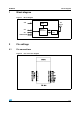
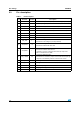
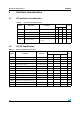
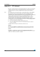
Table Of Contents

Pin settings SPZB260
4/14
2.2 Pin description
Table 1. Pin description
Pin n Pin name Direction Description
1 RSTB I Active low reset ( an internal pull-up of 30 kohm typ is provided)
2 HOST_INT O Host Interrupt Signal ( from ZB Module to Host)
3 SPI_SSEL I SPI Slave Select ( from Host to ZB Module)
4 SPI MOSI I SPI Data , Master Out / Slave In ( from host to ZB Module)
5 SPI MISO O SPI Data , Master In / Slave Out ( from ZB Module to host)
6 SPI_CLK I SPI clock
7 GND --- Ground
8
VDD --- Input power supply
9SIF_CLK I
Non-intrusive debug Interface
Serial interface Clock Signal ( internal pulldown)
10 SIF_MISO O
Non-intrusive debug Interface
Serial interface Master IN/ Slave Out
11 SIF_MOSI I
Non-intrusive debug Interface
Serial interface Master Out/ Slave In
To guarantee a proper signal level when in deep sleep mode
connect a 10kΩ resistor to GND
12 SIF_LOADB I/O
Non-intrusive debug Interface
Serial interface Load strobe ( Open collector with internal pull-up)
To improve noise immunity connect a 10kΩ resistor to V
DD
13 PTI_EN O Frame Signal of Packet Trace Interface (PTI)
14 PTI_DATA O Data Signal of Packet Trace Interface (PTI)
15 WAKE I Wake Interrupt Signal from Host to ZB Module
16 ACTIVITY O Activity signal for application debug /monitor
17 SDBG O