
Datasheet


BTA06 and BTB06 Series
3/7
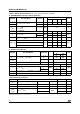
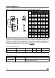
Table 6: Thermal resistance
Symbol Parameter Value Unit
R
th(j-c)
Junction to case (AC)
TO-220AB 1.8
°C/W
TO-220AB Insulated 2.7
R
th(j-a)
Junction to ambient
TO-220AB
TO-220AB Insulated
60 °C/W
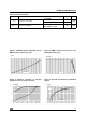
Figure 1: Maximum power dissipation versus
RMS on-state current (full cycle)
Figure 2: RMS on-state current versus case
temperature (full cycle)
Figure 3: Relative variation of thermal
impedance versus pulse duration
Figure 4: On-state characteristics (maximum
values)
0123456
0
1
2
3
4
5
6
7
8
P(W)
I (A)
T(RMS)
0 25 50 75 100 125
0
1
2
3
4
5
6
7
I (A)
T(RMS)
T (°C)
C
BTA
BTB
1E-3 1E-2 1E-1 1E+0 1E+1 1E+2 5E+2
1E-2
1E-1
1E+0
K=[Z /R
th th
]
t (s)
p
Z
th(j-a)
Z
th(j-c)
0.5 1.0 1.5 2.0 2.5 3.0 3.5 4.0 4.5 5.0
1
10
100
I (A)
TM
V (V)
TM
T max.
V = 0.85V
R = 60 m
j
t0
d
Ω
T=
j
T max.
j