
Datasheet


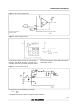
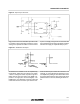
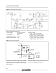


Figure 1 : Error Amp Configuration.
Error amp can source or
sink up to 0.5mA
Figure 2 : UnderVoltage Lockout.
During Under-Voltage Lockout,the outputdriver is
biased to sink minor amounts of current. Pin 6
shouldbe shunted to ground with a bleederresistor
to preventactivatingthe powerswitch with extrane-
ous leakage currents.
Figure 3 : Current Sense Circuit .
Peak current (i
s
) is determinedby the formula
1.0 V
I
S max
≈
R
S
A small RC filter may be required to suppress switch transients.
UC2842/3/4/5-UC3842/3/4/5
5/11