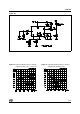
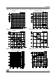
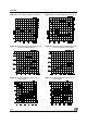
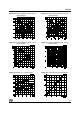
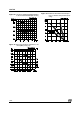
Figure 34 : Junction to Ambient Thermal Resistance
vs. Area on Board Heatsink (DIP 16+2+2)
Figure 35: Maximum Allowable Power Dissipa-
tion vs. Ambient Temperature (Pow-
erdip)
Figure 36: Open Loop Frequency and Phase of Er-
ror Amplifier (see fig. 7C).
L4974A
18/22