
Datasheet

Signal description M24C16, M24C08, M24C04, M24C02, M24C01
10/39 Doc ID 5067 Rev 16
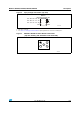
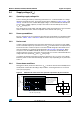
Figure 6. I²C bus protocol
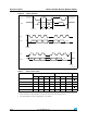
Table 3. Device select code
Device type identifier
(1)
1. The most significant bit, b7, is sent first.
Chip Enable
(2),(3)
2. E0, E1 and E2 are compared against the respective external pins on the memory device.
3. A10, A9 and A8 represent most significant bits of the address.
RW
b7 b6 b5 b4 b3 b2 b1 b0
M24C01 select code 1 0 1 0 E2 E1 E0 RW
M24C02 select code 1 0 1 0 E2 E1 E0 RW
M24C04 select code 1 0 1 0 E2 E1 A8 RW
M24C08 select code 1 0 1 0 E2 A9 A8 RW
M24C16 select code 1 0 1 0 A10 A9 A8 RW
SCL
SDA
SCL
SDA
SDA
Start
condition
SDA
Input
SDA
Change
AI00792c
Stop
condition
1 23 7 89
MSB
ACK
Start
condition
SCL
1 23 7 89
MSB ACK
Stop
condition