
Datasheet


M24C16, M24C08, M24C04, M24C02, M24C01 List of figures
Doc ID 5067 Rev 16 5/39
List of figures
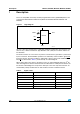
Figure 1. Logic diagram . . . . . . . . . . . . . . . . . . . . . . . . . . . . . . . . . . . . . . . . . . . . . . . . . . . . . . . . . . . . 6
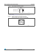
Figure 2. 8-pin package connections (top view) . . . . . . . . . . . . . . . . . . . . . . . . . . . . . . . . . . . . . . . . . 7
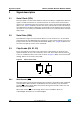
Figure 3. M24C08-F WLCSP and thin WLCSP connections
(top view, marking side, with balls on the underside) . . . . . . . . . . . . . . . . . . . . . . . . . . . . . 7
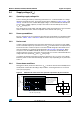
Figure 4. Device select code . . . . . . . . . . . . . . . . . . . . . . . . . . . . . . . . . . . . . . . . . . . . . . . . . . . . . . . . 8
Figure 5. Maximum R
P
value versus bus parasitic capacitance (C) for an I²C bus . . . . . . . . . . . . . . 9
Figure 6. I²C bus protocol . . . . . . . . . . . . . . . . . . . . . . . . . . . . . . . . . . . . . . . . . . . . . . . . . . . . . . . . . 10
Figure 7. Write mode sequences with WC
= 1 (data write inhibited) . . . . . . . . . . . . . . . . . . . . . . . . . 13
Figure 8. Write mode sequences with WC
= 0 (data write enabled) . . . . . . . . . . . . . . . . . . . . . . . . . 14
Figure 9. Write cycle polling flowchart using ACK . . . . . . . . . . . . . . . . . . . . . . . . . . . . . . . . . . . . . . . 15
Figure 10. Read mode sequences . . . . . . . . . . . . . . . . . . . . . . . . . . . . . . . . . . . . . . . . . . . . . . . . . . . . 16
Figure 11. AC measurement I/O waveform . . . . . . . . . . . . . . . . . . . . . . . . . . . . . . . . . . . . . . . . . . . . . 22
Figure 12. AC waveforms . . . . . . . . . . . . . . . . . . . . . . . . . . . . . . . . . . . . . . . . . . . . . . . . . . . . . . . . . . 25
Figure 13. WLCSP (0.5 mm) and Thin WLCSP (0.3 mm) 0.4 mm pitch 5 bumps,
package outline . . . . . . . . . . . . . . . . . . . . . . . . . . . . . . . . . . . . . . . . . . . . . . . . . . . . . . . . . 26
Figure 14. SO8 narrow – 8 lead plastic small outline, 150 mils body width, package outline . . . . . . . 28
Figure 15. UFDFPN8 (MLP8) 8-lead ultra thin fine pitch dual flat package no lead
2 x 3 mm, outline . . . . . . . . . . . . . . . . . . . . . . . . . . . . . . . . . . . . . . . . . . . . . . . . . . . . . . . . 29
Figure 16. TSSOP8 – 8 lead thin shrink small outline, package outline . . . . . . . . . . . . . . . . . . . . . . . 30
Figure 17. PDIP8 – 8 pin plastic DIP, 0.25 mm lead frame, package outline . . . . . . . . . . . . . . . . . . . 31