M48T08 M48T08Y, M48T18 5 V, 64 Kbit (8 Kb x 8) TIMEKEEPER® SRAM Features ■ Integrated ultra low power SRAM, real-time clock, power-fail control circuit, and battery ■ BYTEWIDE™ RAM-like clock access ■ BCD coded year, month, day, date, hours, minutes, and seconds ■ Typical clock accuracy of ±1 minute a month, at 25 °C ■ Automatic power-fail chip deselect and WRITE protection ■ WRITE protect VPFD = power-fail deselect voltage): – M48T08: VCC = 4.75 to 5.5 V; 4.5 V ≤ VPFD ≤ 4.
Contents M48T08, M48T08Y, M48T18 Contents 1 Description . . . . . . . . . . . . . . . . . . . . . . . . . . . . . . . . . . . . . . . . . . . . . . . . . 5 2 Operation modes . . . . . . . . . . . . . . . . . . . . . . . . . . . . . . . . . . . . . . . . . . . . 8 3 2.1 READ mode . . . . . . . . . . . . . . . . . . . . . . . . . . . . . . . . . . . . . . . . . . . . . . . . 9 2.2 WRITE mode . . . . . . . . . . . . . . . . . . . . . . . . . . . . . . . . . . . . . . . . . . . . . . 10 2.
M48T08, M48T08Y, M48T18 List of tables List of tables Table 1. Table 2. Table 3. Table 4. Table 5. Table 6. Table 7. Table 8. Table 9. Table 10. Table 11. Table 12. Table 13. Table 14. Table 15. Table 16. Table 17. Table 18. Signal names . . . . . . . . . . . . . . . . . . . . . . . . . . . . . . . . . . . . . . . . . . . . . . . . . . . . . . . . . . . . 6 Operating modes . . . . . . . . . . . . . . . . . . . . . . . . . . . . . . . . . . . . . . . . . . . . . . . . . . . . . . . . .
List of figures M48T08, M48T08Y, M48T18 List of figures Figure 1. Figure 2. Figure 3. Figure 4. Figure 5. Figure 6. Figure 7. Figure 8. Figure 9. Figure 10. Figure 11. Figure 12. Figure 13. Figure 14. Figure 15. Figure 16. Figure 17. 4/31 Logic diagram . . . . . . . . . . . . . . . . . . . . . . . . . . . . . . . . . . . . . . . . . . . . . . . . . . . . . . . . . . . . 5 DIP connections . . . . . . . . . . . . . . . . . . . . . . . . . . . . . . . . . . . . . . . . . . . . . . . . . . . . . . . . . .
M48T08, M48T08Y, M48T18 1 Description Description The M48T08/18/08Y TIMEKEEPER® RAM is an 8 K x 8 non-volatile static RAM and realtime clock which is pin and function compatible with the DS1643. The monolithic chip is available in two special packages to provide a highly integrated battery-backed memory and real-time clock solution. The M48T08/18/08Y is a non-volatile pin and function equivalent to any JEDEC standard 8 K x 8 SRAM.
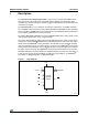
Description M48T08, M48T08Y, M48T18 Table 1. Signal names A0-A12 Address inputs DQ0-DQ7 Data inputs / outputs INT Power fail interrupt (open drain) E1 Chip enable 1 E2 Chip enable 2 G Output enable W WRITE enable VCC Supply voltage VSS Ground Figure 2. DIP connections INT A12 A7 A6 A5 A4 A3 A2 A1 A0 DQ0 DQ1 DQ2 VSS Figure 3.
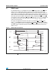
M48T08, M48T08Y, M48T18 Figure 4.
Operation modes 2 M48T08, M48T08Y, M48T18 Operation modes As Figure 4 on page 7 shows, the static memory array and the quartz-controlled clock oscillator of the M48T08/18/08Y are integrated on one silicon chip. The two circuits are interconnected at the upper eight memory locations to provide user accessible BYTEWIDE™ clock information in the bytes with addresses 1FF8h-1FFFh. The clock locations contain the year, month, date, day, hour, minute, and second in 24-hour BCD format.
M48T08, M48T08Y, M48T18 2.1 Operation modes READ mode The M48T08/18/08Y is in the READ mode whenever W (WRITE enable) is high, E1 (chip enable 1) is low, and E2 (chip enable 2) is high. The device architecture allows ripplethrough access of data from eight of 65,536 locations in the static storage array. Thus, the unique address specified by the 13 address inputs defines which one of the 8,192 bytes of data is to be accessed.
Operation modes Table 3.
M48T08, M48T08Y, M48T18 Figure 6. Operation modes WRITE enable controlled, WRITE AC waveform tAVAV VALID A0-A12 tAVWH tWHAX tAVE1L E1 tAVE2H E2 tWLWH tAVWL W tWHQX tWLQZ tWHDX DQ0-DQ7 DATA INPUT tDVWH AI00963 Figure 7.
Operation modes Table 4.
M48T08, M48T08Y, M48T18 2.3 Operation modes Data retention mode With valid VCC applied, the M48T08/18/08Y operates as a conventional BYTEWIDE™ static RAM. Should the supply voltage decay, the RAM will automatically power-fail deselect, write protecting itself when VCC falls within the VPFD (max), VPFD (min) window. All outputs become high impedance, and all inputs are treated as “Don't care.
Clock operations 3 Clock operations 3.1 Reading the clock M48T08, M48T08Y, M48T18 Updates to the TIMEKEEPER® registers should be halted before clock data is read to prevent reading data in transition. The BiPORT™ TIMEKEEPER cells in the RAM array are only data registers and not the actual clock counters, so updating the registers can be halted without disturbing the clock itself. Updating is halted when a '1' is written to the READ bit, the seventh bit in the control register.
M48T08, M48T08Y, M48T18 Table 5.
Clock operations M48T08, M48T08Y, M48T18 M48T08/18/08Y design, however, employs periodic counter correction. The calibration circuit adds or subtracts counts from the oscillator divider circuit at the divide by 256 stage, as shown in Figure 9 on page 17. The number of times pulses are blanked (subtracted, negative calibration) or split (added, positive calibration) depends upon the value loaded into the five-bit calibration byte found in the control register.
M48T08, M48T08Y, M48T18 Figure 8. Clock operations Crystal accuracy across temperature ppm 20 0 -20 -40 ΔF = -0.038 ppm (T - T )2 ± 10% 0 F C2 -60 T0 = 25 °C -80 -100 0 5 10 15 20 25 30 35 40 45 50 55 60 65 70 °C AI02124 Figure 9.
Clock operations 3.5 M48T08, M48T08Y, M48T18 VCC noise and negative going transients ICC transients, including those produced by output switching, can produce voltage fluctuations, resulting in spikes on the VCC bus. These transients can be reduced if capacitors are used to store energy which stabilizes the VCC bus. The energy stored in the bypass capacitors will be released as low going spikes are generated or energy will be absorbed when overshoots occur. A ceramic bypass capacitor value of 0.
M48T08, M48T08Y, M48T18 4 Maximum ratings Maximum ratings Stressing the device above the rating listed in the absolute maximum ratings table may cause permanent damage to the device. These are stress ratings only and operation of the device at these or any other conditions above those indicated in the operating sections of this specification is not implied. Exposure to absolute maximum rating conditions for extended periods may affect device reliability. Table 6.
DC and AC parameters 5 M48T08, M48T08Y, M48T18 DC and AC parameters This section summarizes the operating and measurement conditions, as well as the DC and AC characteristics of the device. The parameters in the following DC and AC characteristic tables are derived from tests performed under the measurement conditions listed in the relevant tables. Designers should check that the operating conditions in their projects match the measurement conditions when using the quoted parameters. Table 7.
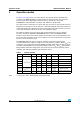
M48T08, M48T08Y, M48T18 Table 9. DC and AC parameters DC characteristics Symbol M48T08/M48T18/T08Y Test condition(1) Parameter Unit Min ±1 µA ±1 µA Outputs open 80 mA Supply current (standby) TTL E1 = VIH, E2 = VIL 3 mA Supply current (standby) CMOS E1 = VCC – 0.2V, E2 = VSS + 0.2V 3 mA Output leakage current Supply current ICC ICC1 0V ≤ VIN ≤ VCC 0V ≤ VOUT ≤ VCC Input leakage current ILI ILO(2) (3) ICC2(3) Max VIL Input low voltage –0.3 0.8 V VIH Input high voltage 2.
DC and AC parameters Table 10.
M48T08, M48T08Y, M48T18 6 Package mechanical data Package mechanical data In order to meet environmental requirements, ST offers these devices in different grades of ECOPACK® packages, depending on their level of environmental compliance. ECOPACK® specifications, grade definitions and product status are available at: www.st.com. ECOPACK® is an ST trademark. Figure 13.
Package mechanical data M48T08, M48T08Y, M48T18 Figure 14. SOH28 – 28-lead plastic small outline, 4-socket battery SNAPHAT®, package outline A2 A C B eB e CP D N E H A1 α L 1 Note: SOH-A Drawing is not to scale. Table 13. SOH28 – 28-lead plastic SO, 4-socket battery SNAPHAT®, package mech. data mm inches Symb Typ Min A Typ Min 3.05 Max 0.120 A1 0.05 0.36 0.002 0.014 A2 2.34 2.69 0.092 0.106 B 0.36 0.51 0.014 0.020 C 0.15 0.32 0.006 0.012 D 17.71 18.49 0.
M48T08, M48T08Y, M48T18 Package mechanical data Figure 15. SH – 4-pin SNAPHAT® housing for 48 mAh battery & crystal, package outline A1 A2 A eA A3 B L eB D E SHTK-A Note: Drawing is not to scale. Table 14. SH – 4-pin SNAPHAT® housing for 48 mAh battery & crystal, package mech. data mm inches Symb Typ Min A Max Typ Min 9.78 Max 0.385 A1 6.73 7.24 0.265 0.285 A2 6.48 6.99 0.255 0.275 A3 0.38 0.015 B 0.46 0.56 0.018 0.022 D 21.21 21.84 0.835 0.860 E 14.22 14.
Package mechanical data M48T08, M48T08Y, M48T18 Figure 16. SH – 4-pin SNAPHAT® housing for 120 mAh battery & crystal, package outline A1 A2 A3 A eA B L eB D E SHTK-A Note: Drawing is not to scale. Table 15. SH – 4-pin SNAPHAT® housing for 120 mAh battery & crystal, package mech. data mm inches Symb Typ Min A Typ Min 10.54 Max 0.415 A1 8.00 8.51 0.315 .0335 A2 7.24 8.00 0.285 0.315 A3 26/31 Max 0.38 0.015 B 0.46 0.56 0.018 0.022 D 21.21 21.84 0.835 0.860 E 17.
M48T08, M48T08Y, M48T18 7 Part numbering Part numbering Table 16. Ordering information scheme Example: M48T 18 –100 PC 1 E Device type M48T Supply voltage and write protect voltage 08(1) = VCC = 4.75 to 5.5 V; VPFD = 4.5 to 4.75 V 18/08Y = VCC = 4.5 to 5.5 V; VPFD = 4.2 to 4.
Part numbering M48T08, M48T08Y, M48T18 Table 17.
M48T08, M48T08Y, M48T18 8 Environmental information Environmental information Figure 17. Recycling symbols This product contains a non-rechargeable lithium (lithium carbon monofluoride chemistry) button cell battery fully encapsulated in the final product. Recycle or dispose of batteries in accordance with the battery manufacturer's instructions and local/national disposal and recycling regulations.
Revision history 9 M48T08, M48T08Y, M48T18 Revision history Table 18. 30/31 Document revision history Date Revision Changes Dec-1999 1 First Issue 07-Feb-2000 2 From Preliminary Data to Datasheet; Battery Low Flag paragraph changed; 100ns speed class identifier changed (Table 3, 4) 11-Jul-2000 2.1 16-Jul-2001 3 01-Aug-2001 3.1 tFB changed (Table 10); Watchdog Timer paragraph changed Reformatted; SNAPHAT battery table added (Table 17); added temp./voltage info.
M48T08, M48T08Y, M48T18 Please Read Carefully: Information in this document is provided solely in connection with ST products. STMicroelectronics NV and its subsidiaries (“ST”) reserve the right to make changes, corrections, modifications or improvements, to this document, and the products and services described herein at any time, without notice. All ST products are sold pursuant to ST’s terms and conditions of sale.