
Datasheet
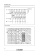
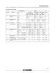


AC ELECTRICAL CHARACTERISTICS (C
L
=50pF,Inputt
r
=t
f
=6ns)
Symbol Parameter
Test Conditions Value
Unit
V
CC
(V)
T
A
=25
o
C
54HC and 74HC
-40 to 85
o
C
74HC
-55 to 125
o
C
54HC
Min. Typ. Max. Min. Max. Min. Max.
t
TLH
t
THL
Output Transition
Time
2.0 30 75 95 110
ns
4.5 8151922
6.0 7131619
t
PLH
t
PHL
Propagation
Delay Time
(CLOCK - Qn)
2.0 92 200 250 300
ns
4.5 26 40 50 60
6.0 20 34 43 51
t
PLH
t
PHL
Propagation
Delay Time
(CLOCK - QS, Q’S)
2.0 65 150 190 225
ns
4.5 19 30 38 45
6.0 15 26 32 38
t
PLH
t
PHL
Propagation
Delay Time
(STROBE - Qn)
2.0 75 160 200 240
ns
4.5 20 32 40 48
6.0 16 27 34 41
t
PZL
t
PZH
3 State Output
Enable Time
2.0 58 150 190 225
ns
4.5 16 30 38 45
6.0 13 26 32 38
t
PHZ
t
PLZ
3 State Output
Disable Time
2.0 35 150 190 225
ns
4.5 16 30 38 45
6.0 13 26 32 38
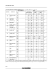
f
MAX
Maximum Clock
Frequency
2.0 6 16 4.8 4
MHz
4.5 30 66 24 20
6.0 35 80 28 24
t
W(H)
t
W(L)
Minimum Pulse
Width
2.0 17 75 95 110
ns
4.5 7151922
6.0 6131619
t
W(L)
Minimum Pulse
Width
2.0 28 75 95 110
ns
4.5 6151922
6.0 6131619
t
s
Minimum Set-up
Time
(SI)
2.0 30 75 95 110
ns
4.5 7151922
6.0 5131619
t
s
Minimum Set-up
Time
(ST)
2.0 45 100 125 145
ns
4.5 10 20 25 29
6.0 8172125
t
h
Minimum Hold
Time
(SI, ST)
2.0 0 0 0
ns
4.5 0 0 0
6.0 0 0 0
C
IN
Input Capacitance 5 10 10 10 pF
C
PD
(*) Power Dissipation
Capacitance
140
pF
(*) C
PD
isdefined as the value of the IC’s internal equivalent capacitance which is calculated from the operating current consumption without load.
(Refer to Test Circuit).Average operting current can be obtained by the followingequation. I
CC
(opr) = C
PD
•V
CC
•f
IN
+I
CC
/2 (per FLIP/FLOP)
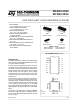
M54/M74HC4094
6/12