
Datasheet


SM6T Characteristics
5/9
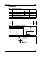
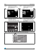
Figure 9. Relative variation of leakage current versus junction temperature
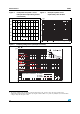
Figure 5. Capacitance versus reverse
applied voltage for unidirectional
types (typical values)
Figure 6. Capacitance versus reverse applied
voltage for bidirectional types
(typical values)
C (pF)
110100
10
100
1000
10000
S
M
6
T
6
V
8
A
S
M
6
T
1
5
A
S
M
6
T
3
0
A
S
M6
T
6
8
A
S
M
6
T
2
2
0
A
V(V)
R
Tj
= 25° C
F= 1 MHz
500
C (pF)
110100
10
100
1000
10000
S
M6
T
6
V
8
C
A
S
M
6
T
1
5
C
A
S
M
6
T
3
0
C
A
S
M
6
T
6
8
C
A
S
M
6
T
2
2
0
C
A
V(V)
R
Tj = 25° C
F= 1 MHz
500
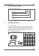
Figure 7. Peak forward voltage drop versus
peak forward current for
unidirectional types (typical values)
Figure 8. Transient thermal resistance
junction to ambient versus pulse
duration (printed circuit board FR4
e
(Cu)
= 35 µm)
0.01 0.1 1 10 100 1000
1
10
100
s
Zth (j-a) (°C/W)
tp
T (° C)
j