
Datasheet


Pin configuration ST662AB, ST662AC
4/20 Doc ID 5068 Rev 8
2 Pin configuration
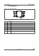
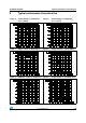
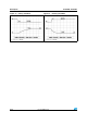
Figure 2. Pin connections (top view)
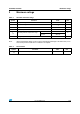
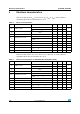
Table 2. Pin description
Pin n° Symbol Name and function
1 C1- Negative terminal for the first charge pump capacitor
2 C1+ Positive terminal for the first charge pump capacitor
3 C2- Negative terminal for the second charge pump capacitor
4 C2+ Positive terminal for the second charge pump capacitor
5V
CC
Supply voltage
6V
OUT
12 V output voltage V
OUT
= V
CC
when in shutdown mode
7 GND Ground
8 SHDN
Active high C-MOS logic level shutdown input. SHDN is internally pulled up to V
CC
.
Connect to GND for normal operation. In Shutdown mode the charge pumps are turned
off and V
OUT
= V
CC