
Datasheet

Symbol Parameter Value Unit
R
th (j-c)
Junctionto case Per diode 1
°
C/W
Total
0.55
R
th (c)
Coupling
0.1
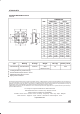
When the diodes 1 and 2 are usedsimultaneously :
∆ Tj(diode 1) = P(diode) x R
th
(Per diode) + P(diode 2) x R
th(c)
THERMAL RESISTANCES
Symbol Parameter TestsConditions Min. Typ. Max. Unit
I
R
*
Reverse leakage current Tj = 25
°
CV
R
=V
RRM
1mA
Tj = 125
°
C
43 150
V
F
* Forward voltage drop Tj = 25°CI
F
= 120 A 0.91 V
Tj = 125°CI
F
= 120 A
0.72 0.87
Tj = 125°CI
F
=60A
0.52 0.67
STATIC ELECTRICAL CHARACTERISTICS
(per diode)
Pulse test : * tp = 380
µ
s,
δ
<2%
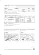
To evaluate the conduction losses use the following equation :
P = 0.47 x I
F(AV)
+ 0.00333 x I
F
2
(RMS)
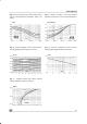
0 25 50 75 100 125 150
0
10
20
30
40
50
60
70
Tamb(°C)
IF(av)(A)
Rth(j-a)=5°C/W
Rth(j-a)=Rth(j-c)
T
δ
=tp/T
tp
Fig. 2: Average current versus case temperature
(
δ
= 0.5) (perdiode).
0 1020304050607080
0
5
10
15
20
25
30
35
40
45
50
55
60
IF(av) (A)
PF(av)(W)
T
δ
=tp/T
tp
δ =1
δ= 0.5
δ = 0.2
δ = 0.1
δ = 0.05
Fig. 1: Average forward power dissipation versus
average forward current (perdiode).
STPS12045TV
2/4