
Datasheet


STTH4R02 Characteristics
Doc ID 12360 Rev 4 3/13
To evaluate the conduction losses use the following equation:
P = 0.67 x I
F(AV)
+ 0.04 I
F
2
(RMS)
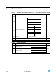
Table 4. Static electrical characteristics
Symbol Parameter Test conditions Min. Typ. Max. Unit
I
R
(1)
Reverse leakage current
T
j
= 25 °C
V
R
= V
RRM
3
µA
T
j
= 125 °C 2 20
V
F
(2)
Forward voltage drop
T
j
= 25 °C I
F
= 12 A 1.15 1.25
VT
j
= 25 °C
I
F
= 4 A
0.95 1.05
T
j
= 150 °C 0.76 0.83
1. Pulse test: t
p
= 5 ms, δ < 2 %
2. Pulse test: t
p
= 380 µs, δ < 2 %
Table 5. Dynamic characteristics
Symbol Parameter
Test conditions
Min. Typ. Max. Unit
t
rr
Reverse recovery time
I
F
= 1 A, dI
F
/dt = -50 A/µs,
V
R
= 30 V, T
j
= 25 °C
24 30
ns
I
F
= 1 A, dI
F
/dt = -100 A/µs,
V
R
= 30 V, T
j
= 25 °C
16 20
I
RM
Reverse recovery current
I
F
= 4 A, dI
F
/dt = -200 A/µs,
V
R
= 160 V, T
j
= 125 °C
4.4 5.5 A
t
fr
Forward recovery time
I
F
= 4 A, dI
F
/dt = 50 A/µs
V
FR
= 1.1 x V
Fmax
, T
j
= 25 °C
80 ns
V
FP
Forward recovery voltage
I
F
= 4 A, dI
F
/dt = 50 A/µs,
T
j
= 25 °C
1.6 V
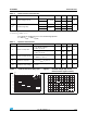
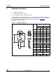
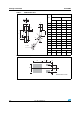
Figure 1. Peak current versus duty cycle Figure 2. Forward voltage drop versus
forward current (typical values)
0
5
10
15
20
25
30
35
40
45
50
0.0 0.1 0.2 0.3 0.4 0.5 0.6 0.7 0.8 0.9 1.0
I
M
(A)
T
d
=tp/T
tp
I
M
T
δ
=tp/T
tp
I
M
P = 2 WP = 2 W
P = 1 WP = 1 W
P = 5 WP = 5 W
δ
I
FM
(A)
0
25
50
75
100
0.0 0.5 1.0 1.5 2.0 2.5 3.0 3.5
T
j
=25°C
T
j
=150°C
V
FM
(V)