
Datasheet


Characteristics STTH4R02
4/13 Doc ID 12360 Rev 4
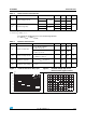
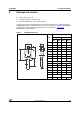
Figure 3. Forward voltage drop versus
forward current (maximum values)
Figure 4. Relative variation of thermal
impedance, junction to case,
versus pulse duration
0
10
20
30
40
50
60
70
80
90
100
0.0 0.5 1.0 1.5 2.0 2.5 3.0 3.5
I
FM
(A)
T
j
=25°C
T
j
=150°C
V
FM
(V)
0.1
1.0
1.E-03 1.E-02 1.E-01 1.E+00
Z
th(j-c)
/R
th(j-c)
Single pulse
TO-220AC
DPAK
tp(s)
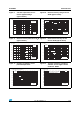
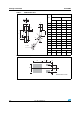
Figure 5. Relative variation of thermal
impedance, junction to case,
versus pulse duration
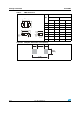
Figure 6. Relative variation of thermal
impedance, junction to ambient,
versus pulse duration (SMB)
0.0
0.1
1.0
1.E-03 1.E-02 1.E-01 1.E+00 1.E+01
Z
th(j-c)
/R
th(j-c)
Single pulse
TO-220FPAC
tp(s)
0.0
0.1
0.2
0.3
0.4
0.5
0.6
0.7
0.8
0.9
1.0
1.E-01 1.E+00 1.E+01 1.E+02 1.E+03
Z
th(j-a)
/R
th(j-a)
SMB
S
Cu
=1cm²
t
p
(s)
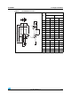
Figure 7. Relative variation of thermal
impedance, junction to ambient,
versus pulse duration
Figure 8. Relative variation of thermal
impedance, junction to ambient,
versus pulse duration (SMC)
1
10
100
1.E-03 1.E-02 1.E-01 1.E+00 1.E+01 1.E+02 1.E+03
Z
th(j-a)
(°C/W)
Single pulse
DO201AB
tp(s)
0.0
0.1
0.2
0.3
0.4
0.5
0.6
0.7
0.8
0.9
1.0
1.E-01 1.E+00 1.E+01 1.E+02 1.E+03
Z
th(j-a)
/R
th(j-a)
SMC
S
Cu
=1cm²
t
p
(s)