
Datasheet


STTH8R06 Characteristics
5/12
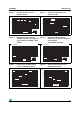
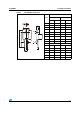
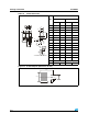
Figure 11. Forward recovery time versus
dI
F
/dt (typical values)
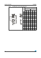
Figure 12. Junction capacitance versus
reverse voltage applied
(typical values)
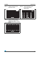
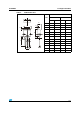
Figure 13. Thermal resistance junction to
ambient versus copper surface
under tab (epoxy FR4, e
CU
= 35 µm)
(D
2
PAK)
0
20
40
60
80
100
120
140
160
0 100 200 300 400 500
t (ns)
fr
dI /dt(A/µs)
F
I=I
T =125°C
FF(AV)
j
V =1.1 x V max.
FR F
10
100
1 10 100 1000
C(pF)
V (V)
R
F=1MHz
V =30mV
T =25°C
OSC RMS
j
0
10
20
30
40
50
60
70
0 5 10 15 20 25 30 35 40
S(Cu)(cm²)
R (°C/W)
th(j-a)